Thursday, January 21, 2010

Arduino Motion Control over Ethernet

Watching the numbers on Google Analytics definitely tells me my reading public doesn't care about my welding projects! So, let's get back to the Arduino.
When I set up to do my POP3 project, I ended up buying an Arduino Ethernet shield and an Adafruit Ethernet shield plus a Lantronix Xport. Having both, I figured it would be a good challenge to get both talking to each other and the result is this fairly simple project which actually ended up taking a lot of thought. It is loosely based on "Networked Game" project in Tom Igoe's indispensable book "Making Things Talk", but Tom's example does the much harder job of writing everything in the low-level serial commands to the Xport while I am lazy and used the published libraries! The challenge here is that the two network shields have two different Arduino libraries which really don't work quite the same way. Also, the Adafruit library is pretty light on explanation and the examples provided have no comments in the code!
Here is the basic setup of this project, basically the accelerometer on the "server" controls two servos on the "client":

The servos, of course, could be hooked up to any number of things like the X-Y axis of a camera mount or a motion base for a game of some kind. Conceptually, of course, through the magic of the Internet and with the right networking setup, the client could be in New York and the server in Instanbul. Also, through the miracle of standard IP protocols I can use one make of shield to successfully communicate with another using two totally different libraries!
Here is a quick video of the rig in action:
Note that the servos jitter slightly when they are hooked up because of slight variations of the analog readings on the accelerometer. I could probably do some averaging to smooth out the readings to eliminate that jitter.
The Server
The server is actually very simple. I used the Adafruit ADXL335 accelerometer (info) that is hooked up to the first three analog pins on the Arduino Diecimilia. The Arduino reads and sends out the X, Y and Z axis, but the client only uses the X and Y values because I only have two servos. It would be pretty easy to build support in for all three axes on the client. Apart from the accelerometer, the only other component is the LED that indicates connected or not connected.


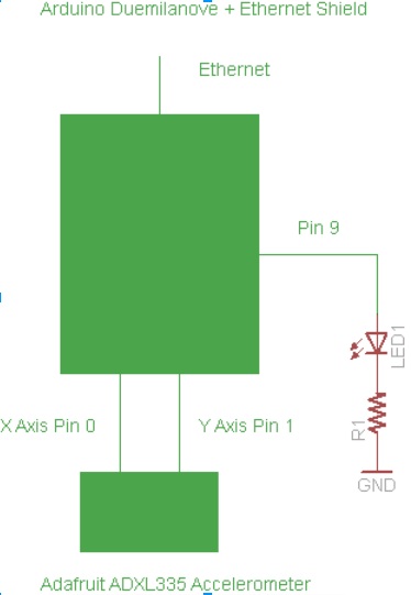

The code is equally simple. It reads the accelerometer and when it receives a "g" from the client it prints out the X, Y & Z readings. When it receives an "x" it ends the session. That's it! Note that this uses the Ethernet.h library distributed with the Arduino software.

* Simple Ethernet Server
*
* A simple server that shows the value of the analog input pins 0 - 2 
* which are connected to an ADXL335 Accelerometer.

by Chris Armour, Jan 2010
*/

#include 

byte mac[] = { 0xDE, 0xAD, 0xBE, 0xEF, 0xFE, 0xED }; //Setting the MAC address
byte ip[] = { 192, 168, 0, 177 }; //IP address of the server
int XPin = 0;
int YPin = 1;
int ZPin = 2;
int ValX = 0;
int ValY = 0;
int ValZ = 0;
int ledPin = 9;
char c;

Server server(54321); //This is the port the server listens on.

//==============Setup pins, server & serial ===================//

void setup()
{
Ethernet.begin(mac, ip);
server.begin();
Serial.begin(9600);
pinMode(ledPin, OUTPUT); 
digitalWrite(ledPin, LOW);
}

//=====================Main loop =============================//

void loop()
{
digitalWrite(ledPin, LOW); //If there is no client connected the LED is off.
Client client = server.available();

while (client.connected()) {

if (client.available()) {
digitalWrite(ledPin, HIGH);  
char c = client.read(); //Read one character at a time.
Serial.print("Value received:  ");
Serial.println(c); 

if (c == 'g') { //"g means "get"
ValX = analogRead(XPin);
ValY = analogRead(YPin);
ValZ = analogRead(ZPin);
Serial.print("Value sent:  ");
Serial.print(ValX);
Serial.print(",");
Serial.print(ValY);
Serial.print(",");
Serial.println(ValZ);
client.print(">");
client.print(ValX);
client.print(",");
client.print(ValY);
client.print(",");
client.println(ValZ);
break;
}
if (c == 'x'){ //x means kill the session.
digitalWrite(ledPin, LOW); //turn off the LED
client.flush();
client.stop();
}
}
}
delay(50);
}

The Client

The client is a slightly more complex beast in that it has a switch to initiate a connection, an LED to indicate the connection state and the servos:


The code is also somewhat more involved. Part of that is because of using the AF_Xport library from Adafruit which takes a bit more fiddling, but also because the client needs the extra logic to initiate and disengage the connection. The main problem area is on resetting the Xport which doesn't always seem to want to connect on the first try so I had to build a loop in to retry the reset until it connects. This is a bit inelegant, but it looks like others have had this problem too.

/*
A network client based on Adafruit Ethernet Shield using the 
Xport ethernet-to-serial adapter. It moves servos based on analog
input from a server with an ADXL335 Accelerometer.

by Chris Armour, Jan 2010
*/

#include 
#include 
#include 
#define XPORT_RXPIN 2
#define XPORT_TXPIN 3
#define XPORT_RESETPIN 4
#define XPORT_DTRPIN 5
#define XPORT_CTSPIN 6
#define XPORT_RTSPIN 7
#define IPADDR "192.168.0.177" //IP Address of the Arduino Server
#define PORT 54321 //IP port of the server

AF_XPort xport = AF_XPort(XPORT_RXPIN, XPORT_TXPIN, XPORT_RESETPIN, XPORT_DTRPIN, XPORT_RTSPIN, XPORT_CTSPIN);

uint8_t ret; //The return variable needs to be formated as a unsigned integer of length 8 bits 
int Xval = 0;
int Yval = 0;
int Xservo = 0;
int Yservo = 0;
int buttonPin = 11;
int buttonWas = 0;
int buttonIs = 1;
int ledState = 0; //I believe these are actually flipped 0 = On 1 = off
int ledPin = 13;
boolean ConnectState = false;
char linebuffer[16]; //Very small line buffer because we just need the X-Y readings.
Servo Xservobj;
Servo Yservobj;
int loopCount = 0;

//===============Setup pins, servo, xport ==========//
void setup()  
{
 pinMode(buttonPin, INPUT);
 pinMode(ledPin, OUTPUT);
 Serial.begin(9600);
 xport.begin(9600);
 delay(300);
 Serial.println("Finished Setup...");
 Xservobj.attach(9);
 Yservobj.attach(8);
 buttonIs = digitalRead(buttonPin);
}

//===============Functions===================//

void getButton() { 
  buttonWas = buttonIs; // Set the old state of the button to be the current state since we're creating a new current state. 
  buttonIs = digitalRead(buttonPin); //Read the buttong state.
}

void errorBlink(){ //Flash 4 times for an error
     for (int x=0; x <=3; x++){  
   digitalWrite(ledPin, HIGH);  
    delay(100);  
    digitalWrite(ledPin,LOW);  
    delay(100);  
   }  
}

char * resetXport(){ //Handles the regular reset of the Xport, returns reset errors
        ret = xport.reset();
       switch (ret) {
          case  ERROR_TIMEDOUT: {
           Serial.println("Timed out on reset!");
           errorBlink();
         return 0;
      }
      case ERROR_BADRESP:  {
         Serial.println("Bad response on reset!");
         errorBlink();
         return 0;
    }
  case ERROR_NONE: {
     Serial.println("Reset OK!");
     break;
    }
    default:
      Serial.println("Unknown error");
      errorBlink();
      return 0;
       }
  delay(250);
}


char * ConnectToggle(){ //This function turns the connection on or off
  
  if (ledState == 1){ //if the LED is off, then the client is not connected.
  resetXport(); //run the reset function
  ret = xport.connect(IPADDR, PORT);
  switch (ret) { //swtich case handles various error states
    case  ERROR_TIMEDOUT: {
     Serial.println("Timed out on connect");
      ConnectState = false;
      errorBlink();
     return 0;
  }
  case ERROR_BADRESP:  {
     Serial.println("Failed to connect");
      ConnectState = false;
      loopCount++;
      Serial.print("Loop count =");
      Serial.println(loopCount);
      ConnectToggle();
      if (loopCount >  2){  //For reasons I have not been able to figure out, it usually takes two tries to connect    
         errorBlink();
         ConnectState = false;
         break;
  }
  }
  case ERROR_NONE: {
    Serial.println("Connected..."); 
    ConnectState = true;
    Serial.println(ConnectState);
    digitalWrite(ledPin, HIGH);
    ledState = 0;
    loopCount = 0;
    break;
  }
  default:
    Serial.println("Unknown error");
     ConnectState = false;
     errorBlink();
    return 0;
 }
 }
  else { //Toggle off connection
    ledState = 1;
    digitalWrite(ledPin, LOW); //turn OFF the LED
    xport.println("x"); //Send the x command that kills the session.
    delay(100); 
    xport.disconnect(); 
    Serial.println("Disconnected.");
    ConnectState = false;
  }
}

void fetchStuff() { //Gets the linebuffer
   xport.flush(100);
   xport.println("g"); 
   ret=xport.readline_timeout(linebuffer, 16, 200); // get first line
   while(ret!=0){
     ret=xport.readline_timeout(linebuffer,16,200);
  }
}

void moveServos(){ //Note that the server sends out the X, Y & Z values, but Z is not used. It could be.
   Xval = (((linebuffer[1] - 48) * 100) + ((linebuffer[2] - 48) * 10) + (linebuffer[3] - 48)); //Extract X value & convert the ASCII to integers
//  Serial.print("Xval:  ");
//  Serial.println(Xval, DEC); 
  
  Xservo = map(Xval, 275, 425, 0, 180); //Map the range of X values from the server to the servos
   Serial.print("Xservo:  ");
  Serial.println(Xservo, DEC);
  Xservobj.write(Xservo);
  delay(15);  
   
   Yval = (((linebuffer[5] - 48) * 100) + ((linebuffer[6] - 48) * 10) + (linebuffer[7] - 48));//Extract Y value & convert the ASCII to integers
//   Serial.print("Yval:  ");
//   Serial.println(Yval, DEC); 

  Yservo = map(Yval, 275, 425, 0, 180); //Map the range of Y values from the server to the servos
   Serial.print("Yservo:  ");
  Serial.println(Yservo, DEC);
  Yservobj.write(Yservo);
  delay(15);     
}
  
//==============Main loop==================//

void loop()   { // run over and over again

getButton(); //Run to check if button has been pressed.

if((buttonIs == 1) && (buttonWas == 0)){
  ConnectToggle(); //If there is a change in the button state, toggle the connection on or off.
}

if (ConnectState == true){ //If the client is connected, do some work!!
  fetchStuff();
  moveServos();
  }
}

Further work
The system needs a way to detect dropped connections - possibly using "millis()" to determine if a response or query has taken too long. As well, I really should smooth out those analog readings so the servos don't jitter! As well, I might just build a motion ase of some sort to hook up to the servos so they can do something slightly more cool that just flap their arms.
So, that's my first Arduino project in a few months! Thanks for the comments and questions. The site has apparently had over 11,000 hits, which completely amazes me. Please keep the comments and suggestions coming. I think next up will be another Chinese knock-off phone review.


Monday, December 14, 2009

Gianttech Plasma Cutter

As mentioned in the previous post, I have bought a plasma cutter a short while ago from the good folks at http://www.plasmametalcutter.com/. Since I only have 110 service in the garage, I had to opt for the Cut40D model (which is confusingly called the Slice40D on the face of the unit). This model features auto-switching between 110 and 220. It comes with a 220 plug on the end, but it is easy enough to switch it for a 110 style plug. I opted for the 110 20 AMP style plug.

All in all, it is a very good study unit. It slices through sheet metal like it isn't even there and so far does fine up to at least 1/4" mild steel. I haven't yet tried it out on thicker stock, but I'm not sure if it could go to a full 1/2" or not. Most of my projects are with 1/8" angle iron stock and it blasts through that with no problem. Like welding, you need to watch the safety precautions and it takes some practise to make steady cuts - especially straight lines.

The Gianttech folks I bought the unit off of were very helpful, however shipping up here to Canada took quite a while, but as a hobbyist I wasn't in a huge hurry. I also bought the package of extra consumables available for the unit since I read that these can be used up quickly. I have had to change the tip once, but I think that is because I fried it when I was learning how to use the unit. Now that I have more practise, I am not noticing much deterioration of the tip or other consumables.

I also had to upgrade my air compressor to an 8 gallon 2+ HP unit. I ended up buy this unit from Boss Tools. It is a very sturdy compressor that seems to deliver loads of pressure! While the Cut40D comes with a combination air regulator and filter, on the advice of my welding teacher, I also added in an extra filter (this item). Apparently, the drier and cleaner the air, the better the cutting and the longer the consumables will last.

Here is a quick video of the cutter in action (note that I keep calling it the "Slice40D" since that is what the face of the unit says):


I only had a couple of small issues with the unit. Like many Chinese tools, the manual was laughably short. My Lincoln Electric MIG welder came with an encyclopedia compared to the Gianttech cutter! However, what was there was adequate to get started.

Another issue was that I initially got a lot of air leakage from the hoses connecting the regulator/filter unit to the cutter. First, I replaced the hose clamps and that mostly fixed it, then I replaced the 1/4" NPT-hose barb fitting off of the regulator and that fixed it. Again, pretty small stuff, and I suppose typical of the small "fit and finish" items you find on Chinese tools (my lathe & milling machine also needed minor tweaks). For the money, I am frankly amazed with how well it works. If I were running a full welding shop, I would probably opt for a heavy duty Miller machine or something, but for a "weekend warrior" hobbyist like me it works great!

Plasma Cutting Table

Plasma Cutting Table

Maintaining my blistering pace of a posting every month or so, here is another project write-up along the metal working lines. I recently bought a Gianttech plasma cutter from the good people at http://www.plasmametalcutter.com (which I will post about shortly). It became obvious pretty quickly that just cutting things on the edge of the welding table wouldn't work very well - and risked damaging my beautiful 3/16 steel top for the welding table. So, the answer was to build a simple plasma cutting table.

At it's most basic, a plasma cutting table is just a set of steel slats turned on their end that conduct electricity to the workpiece, but won't interfere with the cutting action because of their thin profile. I decided that the most reasonable design was to go for 1 1/5" slats of 1/8" thick mild steel. I also figured that the grating part of the table would take a lot of abuse from cutting so it would be good to make it so it could be easily turned over and eventually replaced. The basic idea then was to build the grate as one unit, then have it be able to be set onto the base frame to make the completed table. The base frame is made from good ol' 1 1/2" x 1/8" angle iron. The table surface area is 2' x 2'.


The first parts that I made (which I didn't take pictures of) were two angle iron squares. One makes up the top frame and the other is the cross brace for the legs.

Here is the construction process for the grate - I just used corner clamps to keep adding in more and more slats. They are positioned just slightly over 1 1/2" apart so they space out evenly:


When it was done - and with a bit of grinding and fitting - the grate fit perfectly into the top frame:


Here are the grate, squares and legs waiting for assembly:


...and here is the completed unit:


Ah, the astute observer will notice, why isn't the grate nestled neatly in the top frame the way it was designed? Because i managed to weld it together upside down! Arrgghh! Another lesson that WELDING IS PERMANENT! Double check everything before reaching for the welding gun. However, I was able to weld some extra angle iron onto the top frame to hold the grate. So, it ends up being an inch or so higher than I might have liked, but otherwise is very usable and the top is still easily replaceable:


It's all stores up nice and compact and when I need to work, I can just swing the welder and cutter out on their trolley.

Monday, November 16, 2009

My Welding Cart

Having finished up my welding table, the next step was to have something to actually put my welder on rather than having it sit on the floor. So, I built the following which is based on a plan from "Welding Complete" from Creative Publishing International (available from Amazon here). However, I needed to modify the original plan to make it a bit wider so my plasma cutter would have a place to stay.

Here is the drawing- which omits the wheels which were just purchased from the local home center:


I won't bother going through all the build since it was basically the same as the welding table, but one thing I forgot to get a picture of was the correct way to align the upright components for welding, which is like this:


Use a carpenter's square to ensure the uprights are at a perfect 90 degrees before welding! I missed this crucial step with one of the legs on my welding table and it will be ever so slightly out of square forever now. Welding is definitely a measure THREE times, cut once, measure TWO MORE TIMES then weld type of process.

Here is the whole frame before painting. The hooks are to hang cables off of, but I am a bit worried I will be catching my knees on them.


Finally, a good thick coat of tractor green paint covers a multitude of sins! Actually, we have a pool pump in the same garage as the welding gear and occasionally small amounts of chlorine gas seep out and rust steel instantly, so I really need to paint everything to preserve it. I also put the rubber matting on the help protect the finish and provide some extra electrical insulation.


Here is the whole team! Note that the welding cart is extra wide so the plasma cutter can go beside it.


Next up... Bringing some order to my chaotic garage and workshop, which is hardly a project worth blogging about! I will be welding up some shelves and cabinets as part of the process and I will post that later. I also promise to get back to the Arduino soon. I have another Ethernet shield I haven't yet got assembled and I really want to look at networking two Arduinos together and having them do something halfway useful!

Thursday, November 5, 2009

Welding Table Construction

In honour of Monty Python's 40th Anniversary... And now for something completely different!

I believe way back in the original start of the blog, I explained that I also did a lot of machining including designing & building steam engines a few years ago. I had always meant to take a welding course, and on a whim I decided to finally do that this fall. So, the last few Saturdays I have been struggling out of bed at 6:30 AM to get into to weld with a huge stick welder (Shielded Metal Arc Welding - SWAM) process. Naturally, I have gotten totally obsessed and decided to get a welder for myself!

Originally, I wanted to get a 240 VAC stick welder, but my friendly neighborhood electrician told me the garage wiring just wasn't up to it, and this is hardly something I want to do inside the house! After some research, I settled on a Lincoln Electric MIG-Pak 140 unit which runs off of regular 120 VAC (similar to this) that does Metal Inert Gas arc welding (aka GMAW - Gas-shielded Metal Arc Welding). Fortuitously, it went on a good sale and I picked up a bottle of C02/Argon shielding gas, a leather welders coat and an auto-darkening welding helmet and I was set!

The technique and setup for the MIG welding is quite different from the big Hobart industrial units I am using in class, but MIG welding is pretty easy to at least pick up the basics of. The good thing with getting used to using the big welder in class is it gives you a very healthy respect for all the safety precautions and you get all the good theory on how everything is supposed to work and the various types of welds as well as the good advice of an experienced instructor.

So, after fooling around with my welder to get a feel for how it performs with various thicknesses of metal and so on, I decided the first traditional project for a starting welder is to build a metal welding table. I need the extra surface space in the shop and I definitely need a metal surface table for arc welding.

Step 1 - I worked up a design to get the rough dimensions and the shopping list for the metal store:


This used 1 1/2 inch square tubing for the legs, 1 1/2 angle iron for the frame and 3/16 thick sheet for the table top.

Step 2 - I bought the table top already cut to size and then cut down the frame and leg pieces from the ten foot lengths I bought. Here are the parts laid out before welding:


Step 2 - First I welded the frame that supports the top. The parts were cut mitered and then I put them on some firebricks on the top itself - on the assumption that the top is more level that the old floor of my garage!


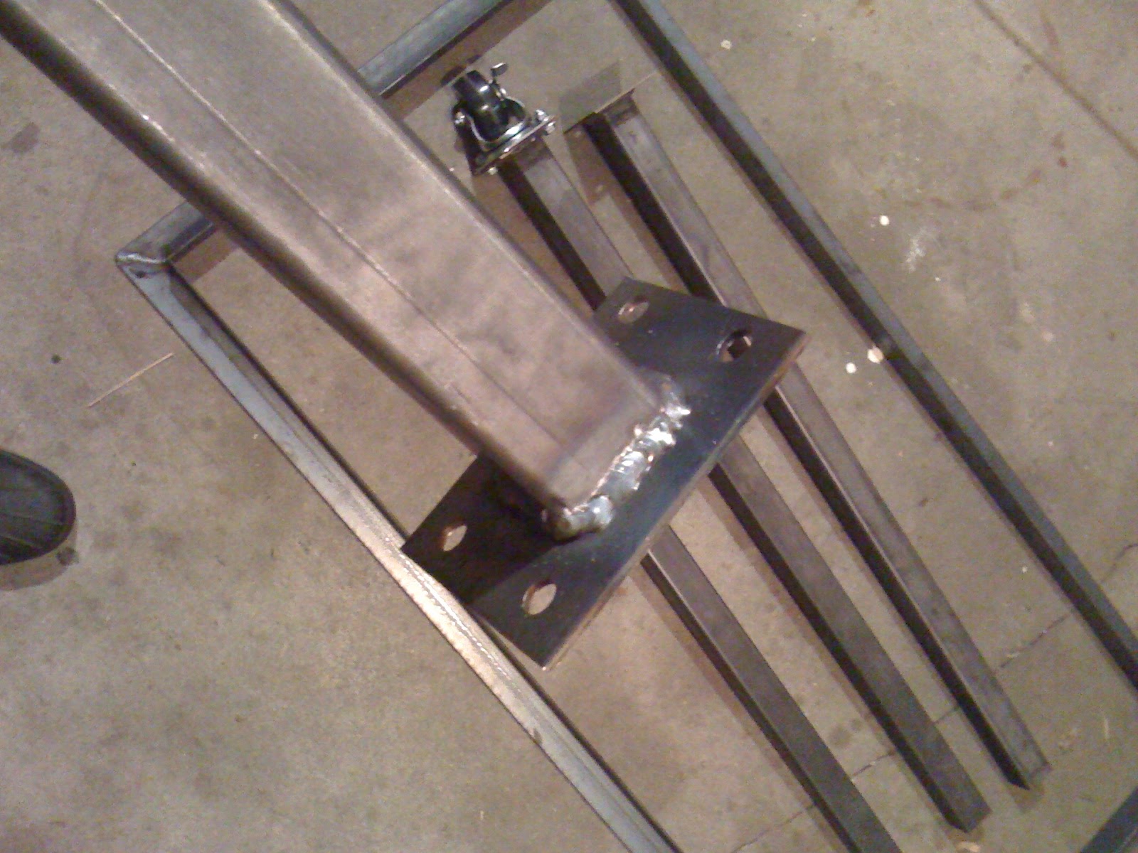
Step 3 - With the top frame done, then I welded the plates for the caster wheels to the bottom of the legs:


Not too bad MIG welds considering I am just starting out!


Step 4 - I welded the leg assemblies to the frame assemblies. I wish I had captured the proper way of lining up the legs perfectly perpendicular to the frame! I actually messed up the first leg and it went on slightly out of true, but the other three legs went on perfectly. You will see later that it's not too bad and the one leg being slightly out won't be too big an impact. Once the legs are welded onto the frame, I needed to grind down the welds on the top of the frame so it would mate properly to the table top:


Step 5 - The frame and leg assembly was welded to the top. Here I use an intermittent rather than a continuous weld:


Step 6 - Roll it out of the shop and paint it! The slats are 1 1/2 inch wide 1/8 thick strapping I added to make a shelf for storing stock and other bits & pieces. Can you tell which leg is slightly out of alignment?


Here it is with good double coat of primer:


Finally, it got a good heavy coat of Tremclad basic green glossy paint so it looks like a tractor!


A nice substantial first welding project and something very useful for the shop! Next up will be a cart to put the welder on and my new plasma cutter which I should get next week.

Some day, I will combine the Arduino, welding and maching stuff into one project, promise!

Tuesday, September 8, 2009

Further on the POP3 email checker

Well, since this project has been a bit of a surpirse hit, I thought I would include a few further notes and refinements.

This is a small change to the updateClient function that just flashes the LED rapidly four times to indicate the network is down:


void updateClient() //This function contacts the POP3 server
{
if ((millis() - updateTimer) > 5000)
{
Ethernet.begin(mac, ip);
// Serial.println("connecting...");
delay(1000);
if (client.connect())
{
// Serial.println("connected");
client.println("user Pop.User"); //Insert your usual email login name
client.println("pass YourPassword"); //And your password here
client.println("quit");
client.println();
clientConnected = true;
}
else
{
// Serial.println("connection failed");
// Flash four time rapidly to indicate network down.
for (int x = 0; x < 4; x++){
digitalWrite(ledPin, HIGH);
delay(100);
digitalWrite(ledPin, LOW);
delay(100);
}
}
updateTimer = millis();
}
}


What is odd is that when I have tried this with another LED it blinks very dimly - even when I move around which digital pin the other LED is coming from. Very odd and I still haven't figured out what is causing that.

Another thing to watch for is that this assumes that the number of emails comes through in array position 106 & 107 (I then subtract 48 to make the ASCII code into an integer):


mailNum1 = inString[106] - 48; //Array position 106 contains the first digit
mailNum2 = inString[107] - 48; //Array position 107 contains the 2nd digit if it is available


This, of course, may vary depending on how many characters there are in your POP3 server name and so on. I would recommend starting with the basic commands for getting the POP3 string back:


#include <Ethernet.h>

byte mac[] = { 0xDE, 0xAD, 0xBE, 0xEF, 0xFE, 0xED };
byte ip[] = { 192,168,0,172 };
byte server[] = { XXX, XXX, XXX, XXX }; // IP address of your POP3 server

Client client(server, 110);

long updateTimer;
boolean clientConnected = false;

void setup()
{
Serial.begin(9600);
}

void loop()
{
updateClient();
checkAvail();
}

void updateClient()
{
if ((millis() - updateTimer) > 10000)
{
Ethernet.begin(mac, ip);
Serial.println("connecting...");
delay(1000);
if (client.connect())
{
Serial.println("connected");
client.println("user user.name"); //Insert your usual email login name
client.println("pass YourEmailPassword"); //And your password here
client.println("quit");
client.println();
clientConnected = true;
}
else
{
Serial.println("connection failed");
}
updateTimer = millis();
}
}

void checkAvail()
{
if (clientConnected)
{
if (client.available())
{
char c = client.read();
Serial.print(c);
}
if (!client.connected())
{
Serial.println();
Serial.println("disconnecting.");
client.stop();
clientConnected = false;
}
}
}


Then watching the output in the serial window, which will look something like:


connecting...
connected
+OK hello from popgate 2.43 on pop108.xxx.xxx.xxx.xxx.xxx
+OK password required.
+OK maildrop ready, 0 messages (0 octets) (16335883)
+OK server signing off.

disconnecting.


You can then use this output to figure out the right position in the array for mailNum1 & mailNum2.

Hope that helps someone out there. It has been very flattering to see how many folks are interested in building this for themselves. As I explained in the first post, once you have the raw number of emails as an integer you can process with Arduino, you can do all sorts of interesting things beyond just flashing and LED!

Thursday, September 3, 2009

Arduino POP3 Email Checker

Since it turns out people actually occasionally READ this blog, I decided it was time to go back to do an Arduino project and try something different. Since I hadn't done any Arduino work with the Internet before, I decided to try something I thought would be relatively simple - having the Arduino check my email and give me some sort of visual indication of how many emails I have. I started out with:
Both were bought from the good people at Robotshop.ca.


These are just combined with a high intensity LED - which really should have a resistor and will have one eventually!


Here is a quick video - sorry it is a bit murky and the LED is a bit bright!


This was actually probably the hardest Arduino code I ever wrote! For one thing, I hadn't done anything substantial with the Arduino for a while and I found I had forgotten much of what I thought I knew. Also, getting the timing right and getting the number of emails out of the return string actually proved pretty difficult. I made things more difficult for myself by trying to use the String library (formerly TextString), which for some reason didn't return consistent results and was generally not documented and finicky. Then I found the usual LED 13 wouldn't work properly - perhaps because the Ethernet Shield was interfering with it. All-in-all, this small program must have taken me three weeks to write!

I did have a bit of help with the code from Digger450 on the Arduino forum in this exchange, which I am very grateful for!

However, now that it is done, this is a nice little demo of Ardunio on the Internet that does do something at least semi-useful. My next extension may be to hook it up to a servo so that it shows my emails on a physical chart or something. I could also use my SparkFun SerialLCD unit to display the subject lines or something.

Here is the source code:

/*=================================================
Ethernet POP3 Mail Checker & indicator

Checks how many messages are waiting on the POP 3 server
and flashed LED on Pin 9 to indicate number of messages.

It will handle up to 99 messages in the POP3 mailbox.

Uncomment the serial lines for troubleshooting.

Copyright by Chris Armour
3 September 2009
http://opensourceprojects-torchris.blogspot.com/

===================================================*/

#include <Ethernet.h>

byte mac[] = { 0xDE, 0xAD, 0xBE, 0xEF, 0xFE, 0xED };
byte ip[] = { 192,168,0,167 }; // IP address you wish to assign to Arduino
byte server[] = { XXX, XXX, XXX, XXX }; // IP address of your POP3 server
char inString[165]; // Number of characters to be collected
int i = 0;
int mailNum1 = 0; // First digit of the email number
int mailNum2 = 0; // Second digit
int mailTotal = 0; // Total # of messsage
char d;
int ledPin = 9;

Client client(server, 110); //The default POP port is 110

long updateTimer;
boolean clientConnected = false;

void setup()
{
//  Serial.begin(9600);
pinMode(ledPin, OUTPUT);
digitalWrite(ledPin, LOW);
}

void loop()
{
   
updateClient();
d = checkAvail();
if (d >= 10){
getMailNum();
}

}

/*========================================
        Functions
=========================================*/

void updateClient() //This function contacts the POP3 server
{
if ((millis() - updateTimer) > 5000)
{
 Ethernet.begin(mac, ip);
//    Serial.println("connecting...");
 delay(1000);
 if (client.connect())
 {
//    Serial.println("connected");
 client.println("user Your.Name"); //Insert your usual email login name
 client.println("pass PassWord"); //And your password here
 client.println("quit");
 client.println();
 clientConnected = true;
 }
 else
 {
//    Serial.println("connection failed");
 }
 updateTimer = millis();
}
}

char checkAvail() //This checks if there is data available and returns a char
{
if (clientConnected)
{
 if (client.available())
 {
 char c = client.read();
     return(c);
 }
 if (!client.connected())
 {
//    Serial.println();
//    Serial.println("disconnecting.");
 client.stop();
 clientConnected = false;
 }
}
}

int getMailNum() //This actually loads the char returned by checkAvail() and puts in into an array
{
inString[i] = d;
i++;
if (i == 165){
   i = 0;
       client.flush();
       mailNum1 = inString[106] - 48; //Array position 106 contains the first digit
       mailNum2 = inString[107] - 48; //Array position 107 contains the 2nd digit if it is available
       if ((mailNum2 >= 0) && (mailNum2 <= 9)){ //If mailNum2 is present, then it is a two digit mail count
         mailTotal = (mailNum1 * 10) + mailNum2; //when 2 digits are present, multiply the 1st by 10 then add to mailTotal
//            Serial.print("Total emails:  ");
//            Serial.println(mailTotal);
          blinkLED(); //Run the blink function as many times as there are emails
       }
       else {
         if ((mailNum1 >= 0) && (mailNum1 <= 9)){//if there is only one digit, then that is mailTotal
         mailTotal = mailNum1;
//        Serial.print("Total emails:  ");
//        Serial.println(mailTotal);
         blinkLED(); //Blink the LED
         }
         }
     }
 }

void blinkLED(){ //Blinks the LED for as many times as indicated by mailTotal
         for(int x = mailTotal; x >= 1; x--){
           digitalWrite(ledPin, HIGH);
           delay(200);             
           digitalWrite(ledPin, LOW);
           delay(200);
         }
}