Showing posts with label OneWire. Show all posts

Wednesday, May 14, 2014

Bringing it all together!

Over the last four blog posts, I have been working step-by-step on creating a basic sensor network in which my BeagleBone takes information from my BlueLine Innovations PowerCost meter and my DigiX Arduino and presents it in a single web interface. Finally, after around three months, I have this working at a level I feel I can write up.

The source code is available on GitHub here.

The system diagram for this project has now expanded to include the new components:


To see how the DigiX is connected to the OneWire sensor, see my previous post here.

Here is a "family portrait" of the hardware on my desk:


I have also updated the layout of the web interface in Jade to move a few elements off to a sidebar:


Here is the code...

App.js


This takes the code I worked up in the last few projects and wraps into one package. Check out GitHub for the full source, but here are a few of the highlights.

The "getData" function has been updated to include two different Request functions - one for the power and outside temperature from the BlueLine Innovations PowerCost gateway and the other from the DigiX OneWire sensor.


function getData() {
    request({
    uri: "http://192.168.1.33/pcmconfig.htm"
    }, function(error, response, body) {
        if (!error && response.statusCode == 200) {
            var n = body.search("Present Demand");
            usage = body.substr((n + 44), 5);
            usage = usage.trim();
            console.log("Power Usage from PowerCost" + usage);
            var n2 = body.search("Sensor Temp");
            temp = body.substr((n2 + 40), 3);
            temp = temp.trim();
            temp = temp - 2;
            console.log("Temp from PowerCost:" + temp);
        }
    });
    request({
        uri: "http://192.168.1.7:3010/temp"
    }, function(error, response, body) {
        if (error) {
            //If there is an error or the DigiX is unreachable, set the value to an error.
            console.log("Error: DigiX not available");
            tempDigiX = 19.99;
            DigiXAvailable = "FALSE";
            console.log("DigiX status: " + DigiXAvailable);
        }
        else if (!error && response.statusCode == 200) {
            var n = body.search("TEMP:");
            tempDigiX = body.substr((n + 6), 5);
            tempDigiX = tempDigiX.trim();
            console.log("Current temp reading on DigiX: " + tempDigiX);
            DigiXAvailable = "TRUE";
            console.log("DigiX status: " + DigiXAvailable);
        }
    });
    var readingInfo = new Readings({
        temp2: temp,
        usage2: usage,
        DigiTemp: tempDigiX
    });
    readingInfo.save(function(err, readingInfo) {
        if (err) return console.error(err);
        console.dir(readingInfo);
    });
}

//run the above function

setInterval(getData, (process.env.REFRESHINT * 1000));


(See my previous post here on the slightly "hacky" way I get the temp info off of the DigiX.)

The info is them popped into the "readingInfo" object and then into the TingoDB database. Then a 'setInterval" runs the GetData function on the timing set by the REFRESHINT environment variable. If the Request function for the DigiX can't connect then it sets the DigiXAvailable variable to FALSE and also sets the temperature to a nominal "19.99". I played around with various mechanisms to test and flag that the link to the DigiX was up or down and this was the best I could come up with for now. It does have a lot of lag since it won't set the unavailable status on the web page until it has run through a full three minute cycle.

The other big part of App.js is the Socket.io section:

io.sockets.on('connection', function(socket) {
    console.log('A new user connected!');
    Readings.find({}, {}, {
    sort: {
        'time': -1
    },
            limit: process.env.SAMPLES
}, function(err, readings) {
            socket.broadcast.emit('readingsData', readings);
            console.log(process.env.SAMPLES + ' readings sent over');
            console.log('DigiX Status sent over socket = ' + DigiXAvailable);
            socket.broadcast.emit('digiXStatus', DigiXAvailable);
        });
    setInterval(function() {
        Readings.find({}, {}, {
            sort: {
                'time': -1
            },
            limit: process.env.SAMPLES
        }, function(err, readings) {
            socket.broadcast.emit('readingsData', readings);
            console.log(process.env.SAMPLES + ' readings sent over');
            console.log('DigiX Status sent over socket = ' + DigiXAvailable);
            socket.broadcast.emit('digiXStatus', DigiXAvailable);
        });
    }, (process.env.REFRESHINT * 1000));
    socket.on('sampleInput', function(sampleInputSetting) {
        console.log('setting data = ' + sampleInputSetting);
        process.env.SAMPLES = sampleInputSetting;
        socket.broadcast.emit('sampleSetting', sampleInputSetting);
        console.log('Sending sample rate back out');
    });
    socket.on('refreshInput', function(refreshInputSetting) {
        console.log('setting data = ' + refreshInputSetting);
        process.env.REFRESHINT = refreshInputSetting;
        socket.broadcast.emit('refreshSetting', refreshInputSetting);
        console.log('Sending refresh rate back out');
        Readings.find({}, {}, {
            sort: {
                'time': -1
            },
            limit: process.env.SAMPLES
        }, function(err, readings) {
            socket.broadcast.emit('readingsData', readings);
            socket.emit('readingsData', readings);
        });
    });
});

This is pretty similar to the original Socket.io version of my project (check it out here)it's just that now it also sends over the DigiXAvailable flag to the browser for processing to alert end-users of the status of the DigiX.

I really must start using the "Promises" framework in Node to simplify some of these nested functions!


Main.js


On the client side, the codes is again pretty similar to the last version of this project, except now I have included this in the Socket.io section:

    socket.on('digiXStatus', function(digiXStatusData) {
       console.log('DigiX Status received: ' + digiXStatusData);
        if (digiXStatusData == "FALSE"){
            $('#DigiStatus').text('Offline');
            $('#DigiStatus').css('color', 'red');
            } else {
            console.log("DigiX online");
            $('#DigiStatus').text('Online');
            $('#DigiStatus').css('color', 'green');
            }
    });    


This will take the DigiXAvaialble flag from the socket (renamed digiXStatusData when it gets over to the browser) and then write info to the "#DigiStatus" DIV on the webpage using jQuery.


Index.Jade


I decided to change the layout to put a "status" block and the controls off to the left side to make the layout a bit more horizontal. To do this I created CSS elements in Stylesheet.css for the "Status" on the left side and the "Content" area where the chart data goes:

status {
  position: absolute;
  left: 0;
  width: 15em;
}

#content {
  margin-left: 15em;
}


I then created a DIV in Jade and put the content where it belonged:

extends layout

block content    
  #status
    h2 System Status
    table
      tr
        td
          b DigiX:
        td
          #DigiStatus
      tr
        td 
          b BeagleBone:
        td
          #logger 

    h2 Settings
    p Data to graph: 
       input#dataSampleInput(value= '#{sampleNum}', type='text')
    p Time between refresh (sec)
       input#refreshTimeInput(value= '#{refreshRate}', type='text')

    button#submitBtn Submit

  #content
    h1= title

    #legendholder(style='margin-left: 110px;')
    #placeholder(style='width:700px;height:300px')

    h2 Current Readings
    #tablediv
      table
       thead
         tr 
           td 
             b Timestamp
           td
             b Outside Temp
           td
             b Power usage
           td
             b DigiX Temp
         tbody
           tr
             td
               #currTime
             td
               #currTemp
             td
               #currUsage
             td
               #currDigiX


Jade takes some getting used to, but it does allow you to generate a webpage without many lines of code!

DigiX software


This is identical to my post here - the DigiX serves up information depending on which URL is requested. I chose to not implement the digital On/Off controls in this version, but they would be easy enough to include in the future.

Conclusion and next steps


Well, that's about it for this phase. There are a few things I still need to track down...

  • As I said, there is a lot of lag in alerting on the browser if the DigiX goes offline (which it does occasionally) - basically it goes through at least one of it's 180 second cycles. I played around with a "heartbeat" or "ping" function, but I couldn't quite get it to work.
  • Since the DigiX has an SD card slot, it would be good to be able to buffer readings when there is a network interruption and then send them over once the connection is re-established.
  • It would be good to throw an LCD display onto the DigiX to display the sensor readings. 
  • I need to add a few more sensors onto the DigiX as well - light level and humidity, for instance!

Next up, I want to exercise the mesh radio features of the DigiX. A few months back, I bought a few of these NRF24L01+ radios with serial modules off of eBay (check them out here):
I can hopefully use one of these with one of my regular Arduinos just using serial! Check back in a few weeks on that!


Monday, April 21, 2014

Integrating the Beaglebone and DigiX - Part 2 of 2

This is the second part of my adventures with the Digix! In this blog, I will describe the software and the slightly "hackified" way I got the DigiX and my Beaglebone to talk to one another.

The software is all posted to GitHub here:

https://github.com/torchris/digixbeagle

If you missed the first section of this, check it out here.

Hardware setup


Here is a diagram of the breadboard I did up in Fritzing. Note that I have used an Arduino Due instead of the DigiX because there is not yet a DigiX image for Fritzing and the Dues is a similar size and shape.


This is very straightforward and there are many good articles on using the DS18B20 OneWire sensor with the Arduino. Here is an excellent article by Simon Tushev. There are also two LEDs. One shows when requests are being processed and the other shows how a digital output on the DigiX can be controlled by the web page off the BeagleBone.

Server side


The server code for this running on the BeagleBone is a basic Express site modified to use Socket.io and using the Request library to get information from the DigiX. The server then uses Socket.io to push the out to a browser. It also takes input from the browser and sends it back over to the DigiX.

The one thing to note here, which I should have remembered from the last time around is that you can't use the Express template with Socket.io right off the bat. This post from Stackoverflow explains the situation. Just to extract the most salient bit:
Express 3 requires that you instantiate a http.Server to attach socket.io to first:

meaning - (1) you must create a server instance:

var app = express();
var http = require('http').createServer(app);
 
(2) couple it with the socket.io:

var io = require('socket.io');
io.listen(http);
 
and ONLY THEN - (3) make the server listen:

http.listen(8080);
 
make sure you keep this order!
I must tattoo  that on my forehead so I don't waste time with Socket.io not working!!

Anyway, the App.js code is basically all stock except for the change above and this function that gets the info from the DigiX using web page calls and the Request library (more on that later on) and then does some simple text processing to extract the temp.:

function getData() {
    request({
        uri: "http://192.168.1.7:3010/temp"
    }, function(error, response, body) {
        if (error){
            //If there is an error or the DigiX is unreachable, set the value to an error.
            console.log("Error: DigiX not available");
            temp = "DigiX not available";
            }
        else if (!error && response.statusCode == 200) {
            var n = body.search("TEMP:");
            temp = body.substr((n + 6), 5);
            temp = temp.trim();
            console.log("Current temp reading: " + temp);
        }
    });
    setTimeout(getData, 10000);
}
getData();


The other main part of App.js is the Socket.io section:

io.sockets.on('connection', function(socket) {
    console.log('A new user connected!');
    console.log("Sending over initial LED state: " + ledStatOn);
    socket.broadcast.emit('ledStatOn', ledStatOn);
    setInterval(function() {
        socket.broadcast.emit('tempData', temp);
        console.log("Temp sent over sockets to client; " + temp);
    }, 10000);
    socket.on('ledStatOn', function(ledStatOn) {
        if (ledStatOn == "ledOn") {
            console.log('LED data = ' + ledStatOn);
            request({
                uri: "http://192.168.1.7:3010/on"
            }, function(error, response, body) {
                if (!error && response.statusCode == 200) {
                    var x = body.search("ledCmded:");
                    ledOnStat = body.substr((x + 10), 2);
                    ledOnStat = ledOnStat.trim();
                    console.log("LED status is " + ledOnStat);
                    socket.emit('ledStatOn', ledOnStat);
                }
            });
        }
        else if (ledStatOn === "ledOff") {
            console.log('LED data = ' + ledStatOn);
            request({
                uri: "http://192.168.1.7:3010/off"
            }, function(error, response, body) {
                if (!error && response.statusCode == 200) {
                    var x = body.search("ledCmded:");
                    ledOnStat = body.substr((x + 10), 3);
                    ledOnStat = ledOnStat.trim();
                    console.log("LED status is " + ledOnStat);
                    socket.emit('ledStatOn', ledOnStat);
                }
            });
        }
    });

});


When the Socket.io connection is established, this sends over the temerature info from the DS18S20to be displayed on the browser. As well, when commands to turn on or off the LED come over from the browser via Socket.io, the Request library is used to trigger these actions on the DigiX.

Browser side


The web interface for this is very, very simple. Just a basic Jade-generated page:


Here is the JavaScript code for the page:

var socket = io.connect();


$(document).ready(function() {

 socket.on('ledStatOn', function(ledStatOn) {
        console.log('Received LED status ' + ledStatOn);
    });   
    
$("input:radio[name=ledStat]").click(function() {
    var val = $('input:radio[name=ledStat]:checked').val();
    console.log(val);
        socket.emit('ledStatOn', val);
});

    
    socket.on('tempData', function(tempData) {
        $('#logger').text('Web server connected.');
        $('#logger').css('color', 'green');
        console.log("Server Connected");
        console.log(tempData);
        $('#tempData').html(tempData);
        socket.on('disconnect', function() {
            // visually disconnect
            $('#logger').text('Web server disconnected.');
            $('#logger').css('color', 'red');
        });
    
    });
});


This reuses the server connected/disconnected status used in the previous project. It also uses "socket.emit" to send over to teh server the user selection for the digital output on the DigiX.

Index.jade is also pretty simple - just the DIVs to write the info into and the radio buttons for the LED:

extends layout

block content

  h1= title
  p Welcome to #{title}
  #logger
  br
  p Curent temperature from DigiX:
  b#tempData
  br
  br
  input(type='radio', name='ledStat', value='ledOff', checked='CHECKED')
  | LED Off
  input(type='radio', name='ledStat', value='ledOn')
  | LED On


DigiX


This is where it maybe gets a bit silly, but it does work. As I explained in my last post, I couldn't figure out how to get Socket.io or even good-old Websockets (which I used four years ago with this project in PHP). I am sure someone with more brains or patience could easily come up with an answer, but I got impatient to get this going, so I came up with this solution.

I noticed in the DigiX webserver demo application that the DigiX was parsing the value of the page requested (of course it would have to) and I figured that with different pages being called, the sketch could execute different Arduino commands. In other words, to get the application to do something on the on the DigiX, I just called different web addresses. Here is what this sketch implements. When I call these URLs, I get the following responses:
  • http://192.168.1.7/on = turn ON the LED at digital output 8
  • http://192.168.1.7/off = turn OFF the LED at digital output 8
  • http://192.168.1.7/temp = print a simple webpage with the DS18B20 OneWire temp reading
Nice and simple! Also easy to troubleshoot because I can just use any browser to navigate to those pages and see the results. Is this a basic RESTful API? (I use the LED on pin 9 to show when a web request is being processed.)

Here is the code:

#include 
#include 
#include 
DigiFi wifi;
int ledCmded = 8;
int ledStat = 9;
#define ONE_WIRE_BUS 10

// Setup a oneWire instance to communicate with any OneWire devices (not just Maxim/Dallas temperature ICs)
OneWire oneWire(ONE_WIRE_BUS);

// Pass our oneWire reference to Dallas Temperature.
DallasTemperature sensors(&oneWire);

void setup()
{
  pinMode(ledCmded, OUTPUT);
  pinMode(ledStat, OUTPUT);
  digitalWrite(ledCmded, LOW);
  digitalWrite(ledStat, LOW);
  Serial.begin(9600);
  wifi.begin(9600);
  sensors.begin();
  //DigiX trick - since we are on serial over USB wait for character to be entered in serial terminal
  while (!Serial.available()) {
    Serial.println("Enter any key to begin");
    delay(1000);
  }

  Serial.println("Starting");

  while (wifi.ready() != 1)
  {
    Serial.println("Error connecting to network");
    delay(15000);
  }

  Serial.println("Connected to wifi!");
  Serial.print("Server running at: ");
  String address = wifi.server(3010);//sets up server and returns IP
  Serial.println(address);

  //  wifi.close();
}

void loop()
{

  if ( wifi.serverRequest()) {
    Serial.print("Request for: ");
    Serial.println(wifi.serverRequestPath());
    if (wifi.serverRequestPath() == "/off") {
      digitalWrite(ledStat, HIGH);
      digitalWrite(ledCmded, LOW);
      Serial.println("ledCmded off");
      wifi.serverResponse("

ledCmded: OFF

");       digitalWrite(ledStat, LOW);     }     else if (wifi.serverRequestPath() == "/on") {       digitalWrite(ledStat, HIGH);       digitalWrite(ledCmded, HIGH);       Serial.println("ledCmded on");       wifi.serverResponse("

ledCmded: ON

");       digitalWrite(ledStat, LOW);     } else if (wifi.serverRequestPath() == "/temp") {       digitalWrite(ledStat, HIGH);       float gotTemp;       gotTemp = getTemp();       Serial.print("Temp =  ");       Serial.println(gotTemp);       wifi.println("HTTP/1.1 200 OK");       wifi.println("Content-Type: text/html");       wifi.println("Connection: close");  // the connection will be closed after completion of the response       wifi.println();       wifi.println("");       wifi.print("

TEMP: ");       wifi.print(gotTemp);       wifi.print("

");       digitalWrite(ledStat, LOW);     }     else {       wifi.serverResponse("

Nothing doing

"); //defaults to 200     }   }   delay(10); } float getTemp() {   float currTemp;   sensors.requestTemperatures(); // Send the command to get temperatures   currTemp = sensors.getTempCByIndex(0);   Serial.println(currTemp); // Why "byIndex"? You can have more than one IC on the same bus. 0 refers to the first IC on the wire   return currTemp; }


This works as an easy way to get the kind of interaction I wanted for this project, which is just to exchange some simple sensor info in a non-realtime way and test a Server -> Arduino digital output. However, this has some obvious limitations. It would be hard, for instance, to exchange analog information from the server to the Arduino (for instance, to dim an LED using PWM). You could perhaps have the BeagleBone server send over a series of URLs like "http://192.168.1.7/analog789" where "789" is the analog value and the Arduino code parses that out of the request and then sets the PWM value, but I doubt you could do this more than a few times per minute.  In other words, this is a nice easy way to get this project working, but I can't see how you could do something like my earlier project where I exchanged realtime movement info over the network (see this project).

That's it for now. Next up will be to include this DigiX sensor data in my previous code so I start to have a real "sensor network". Eventually, I want to use the mesh networking off of the DigiX to get sensor data from several other Arduinos (hopefully the tiny DigiSparks if I can make them work).


Friday, April 11, 2014

Getting started with the DigiX - Part 1 of 2

This is the first part of my project to integrate the Digistump DigiX board with the BeagleBone. In this post, I'll provide a review of the DigiX and some of the good and less good points about working with it. The next section will describe in more detail the software and process I used to build the project.

First, for your multimedia viewing pleasure,  here is a quick video tour of this fairly simple project:


Introducing the DigiX

The DigiX is produced by DigiStump which was founded in 2012 by Mr. Erik Kettenburg in the Seattle area. I first became aware of them when I backed his successful Kickstarter for the DigiSpark which is a super-small $9 Arduino development board  - I will include them in a later part of my monitoring system. A few months after the DigiSpark shipped, I saw the Kickstarter come up for the DigiX and decided to go for it.

The specs on the DigiX are, frankly over the top! This is the Monster Killer Arduino of all Time (at least for now) - check it out:


In form factor, it looks a bit similar to the Arduino Due, but it has a double row of IO pins down the one side whereas the Due only has a single row.

This is a beast!! As well it has BOTH on-board wifi and mesh networking via the popular, low-cost nRF24L01+ wireless module and and a micro SD card slot. All this for only $69.95 USD!

 That being said, given that the BeagleBone Black is only $44.95 and the RaspBerry Pi is only $39.95 (prices from SparkFun) and both of them run full up Linux. Is it worth the extra money to have the DigiX? Here are a few thoughts on pros and cons...

Pros

  1. Rather than having to wrestle with the complexity of managing GPIO in the Linux environment, the DigiX supports the usual Arduino IDE and it's familiar interface. If you're used to stock Arduinos, then there is no ramp up.
  2. The onboard wifi works as advertised and is a breeze to configure according to the DigiX Wiki article (check it out here).
  3. There are more IO pins than any reasonable person could ever use and there is loads of program memory space (524,288 bytes).
  4. There is a good range of sample programs that exercise the functionality of the board and they all seem to compile and work right away. I was amazed that I had a simple web server up and running in about 15 minutes!
  5. I haven't tried the mesh networking yet, but I am assuming it works and it's awesome to have it on the same board.
  6. This board is a 3.3 VDC board (like the other newer Arduinos), but Digistump sells a level shifting shield so you can reuse older 5 VDC shields, which is very useful if you're an old-timer like me.
  7. There is a reasonable amount of documentation and active forums for help.

Cons


The main draw back is is it not quite a stock Arduino and a couple of compromises have been made to keep the board affordable. Let's look at two things I have found...

Wifi

The wifi module on the DigiX is not the same as on the Arduino Yun. The Yun uses the AR9331 while the DigiX uses an Atheros Silicon based embedded UART/WiFi module(source here). This means the DigiFi wifi library is mostly compatible with the Arduino Ethernet library, but not 100%.

Consequently, for the project I just completed, I wanted to use Socket.io or websockets to exchange information between my Beaglebone and the DigiX. I tried various sockets libraries and just could not find a way to make them work with the DigiX! I posted a thread to the DigiX forums, but, since they're somewhat less active than the Arduino boards, I so far haven't found a solution. You will see in my upcoming project that the solution I found works, but is definitely "suboptimal" from a design standpoint.


USB Serial and programming

Mr. Kettenburg provides a good technical description of what happens with USB serial on the DigiX and Due boards here. You can read the detailed explanation, but what it boils down to is that the Arduino Due has two USB ports - one for programming and one for native USB - while the DigiX has only one USB port which has to work for programming and USB. Unfortunately, on the DigiX it seems to sometimes be a coin toss as to which is going to be available when you boot up the board, which caused me some headaches at first.

When I was first using the board, it would do something like this when doing programming:
  1. The Arduino IDE is set on COM16 and you hit the upload button in the IDE.
  2. The program compiles and if there are no errors, then it goes to upload and says "The COM port isn't available".
  3. Restart the DigiX and if you are lucky it comes up with COM15.
  4. While on COM15, hit the upload button and it goes through and programs the board.
  5. However when you go to the IDE to select the serial port for the serial monitor, it is back to COM16!
This could be a huge hassle sometimes requiring multiple restarts of the board and plugging and unplugging the USB until the right port came up. As well, the IDE serial monitor would sometimes not fire up and that required more restarts.

At the moment, I seem to have solved this and it is working smoothly. What I did was follow this advice from the DigiX wiki:

If the COM port isn't showing in the Arduino IDE - unplug and replug the board. If that doesn't work - while plugged in, hold down the erase button on the board for a moment and then unplug and replug - you may then have to select it from the com port menu as it may be on a different port - but it is a sure way to get it to respond even if your sketch crashed the USB stack. 

At the same time as doing this, I moved it to another USB port on my system and Windows reloaded the drivers. It works normally now, but it leaves me concerned it will stop working again in the future. I guess I shouldn't complain because it is a bit of an RTFM situation, but perhaps future versions of the board could have the two port solution like the Due or maybe a jumper block to put the USB port into one mode or the other to avoid this confusion?

Summary


Despite the minor hassles I would still say the DigiX is a great board and worth the money. It gives you loads of room to grow and build very sophisticated networked projects. If you just want something relatively simple to take some digital/analog inputs and then do some digital.analog outputs, then this board may be too much and you should look at some of the simpler Arduinos on the market.

As the "Internet of Things" movement develops, it will be de rigueur to be able to to hook your embedded project to the Internet and to other devices via either mesh or Bluetooth Low Energy. The DigiX has you covered with wifi and mesh on board and while it is more expensive than some boards, you save by having all the connectivity integrated and not having to get separate shields and so on.

Nest up, the software the drives this project!


Saturday, January 17, 2009

Indoor Outdoor Temp Display

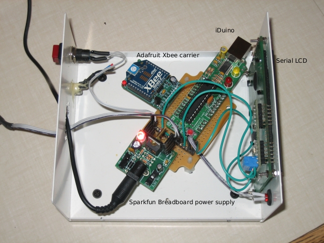
OK, it's time to move on with the remote sensor network description. Now for the Indoor-Outdoor Temp display, which is right now sitting faithfully beside my desk:


This uses a local DS18B20 Onewire temp sensor and the following standard components:


The first four items all came as kits which were assembled in less than 20 minutes. The big advantage of this approach is I am then just gluing together stuff others have built rather than having to build everything from scratch. The Adafruit XBee adapter, for instance, automatically adjusts the voltage down to 3.3 VDC (with the conditioning capacitors) and brings all the connections out neatly rather than having to hunt on the Xbee's pins. Slick.

Here is another hard to interpret schematic (click for full size):
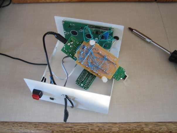
And here it all is installed in a project box I bought from Jameco a while back:


The circuit is built using wire wrap, which is a lightly "olde timey" way to do a circuit board. I rather like it because it is more permanent than a breadboard, but not nearly as much hassle as making a printed circuit board.


Now, what is that switch for? It actually doesn't control the power, but rather is hooked to digital pin 6 on the iDuino. When the switch is tripped, it sends out the "h" command over the Xbee which turns on LED2 on my remote unit. All this really demonstrates is the ability to send simple I/O back to the remote sensor from the indoor display. Not very practical, but remember that this is all just a prototype for something that does real work remotely!

The source code is shown below. The interesting thing is that this uses both the hard serial port on the Arduino and the Lady Ada AFSerial library (click here for more info ) to create a second soft serial port off of pins 2 & 3 on the iDuino. The interesting thing about this is that I found I could NOT use the Arduino software serial library (found here). While I have been able to use this oibrary to send info to the SerialLCD display, it will not receive serial properly - if there is a call to the hardware serial port, then the Arduino software serial port no longer works. The funny thing is the AFSerial library from Laday Ada works perfectly - just like another hardware serial port. No idea why.

Again, a lot of this code is concerned with running the DS18B20 Onewire temperature sensor.

/* Indoor display for Indoor Outdoor thermometer
copyright Chris Armour */

#include 

#define TEMP_PIN  5

AFSoftSerial mySerial =  AFSoftSerial(3,2);
void OneWireReset(int Pin);
void OneWireOutByte(int Pin, byte d);
byte OneWireInByte(int Pin);

int i = 0;
int incomingNumber[4];
int incomingByte = 0;
char outMinusBit = '+';
int outTempDig1 = 0;
int outTempDig2 = 0;
int ButtonPin = 6;
int LEDPin = 12;
int switchState = 0;
long previousMillis = 0;        
long interval = 3000;           

void setup() {
  Serial.begin(9600);
  digitalWrite(TEMP_PIN, LOW);
  pinMode(TEMP_PIN, INPUT);      // sets the digital pin as input (logic 1)
  mySerial.begin(9600);
  pinMode(ButtonPin, INPUT);
  pinMode(LEDPin, OUTPUT);
}

void loop() {

// ======= The following is all code to control the OneWire sensor ==========//
  int HighByte, LowByte, TReading, SignBit, Tc_100, Whole, MinusBit;
  OneWireReset(TEMP_PIN);
  OneWireOutByte(TEMP_PIN, 0xcc);
  OneWireOutByte(TEMP_PIN, 0x44); // perform temperature conversion, strong pullup for one sec

  OneWireReset(TEMP_PIN);
  OneWireOutByte(TEMP_PIN, 0xcc);
  OneWireOutByte(TEMP_PIN, 0xbe);

  LowByte = OneWireInByte(TEMP_PIN);
  HighByte = OneWireInByte(TEMP_PIN);
  TReading = (HighByte << 8) + LowByte;
  SignBit = TReading & 0x8000;  // test most sig bit
  if (SignBit) // negative
  {
    TReading = (TReading ^ 0xffff) + 1; // 2's comp
  }
  Tc_100 = (6 * TReading) + TReading / 4;    // multiply by (100 * 0.0625) or 6.25

  Whole = Tc_100 / 100;  // separate off the whole and fractional portions

//=========> End of the OneWire code MinusBit is the +/- & Whole is the temp ====/
//if (millis() - previousMillis > interval){
//  previousMillis = millis();
 if (Serial.available() > 0) {
//Read the first four characters when serial is received from the Xbee
   for (int i=0; i <= 4; i ++){
 // read the incoming byte:
 incomingByte = Serial.read();
        incomingNumber[i] = incomingByte - 48;
         }
         Serial.flush();
         //Discard the rest
     }
    
    if (incomingNumber[0] == 1) // Test if the first bit in indicates a positive or negative temp.
              {
                outMinusBit = '-';
              }
            else if (incomingNumber[0] == 0)
            {
              outMinusBit = '+';
            }
            outTempDig1 = incomingNumber[2]; //Assign the first digit of the temp
            outTempDig2 = incomingNumber[3]; //Assign the 2nd digit of the temp

  //Clear the LCD screen
  delay(1);
  Serial.print(254, BYTE);
  delay(1);
  Serial.print(1, BYTE); 
  delay(1);

//Print out the inside temp
  Serial.print("Inside Temp: ");
   if (SignBit) // If its negative
  {
    MinusBit = 1; 
    Serial.print("-");
  }
  else
  {
    MinusBit = 0;
    Serial.print("+");
  }
  
delay(1);
Serial.print(Whole);
//Print out the outside temp
Serial.print("    ");
Serial.print("Outside Temp: ");
Serial.print(outMinusBit);
Serial.print(outTempDig1);
//Only print the 2nd digit if there is a positive value
if (outTempDig2 >= 0){
    Serial.print(outTempDig2);
  }
  else {
    Serial.print(" ");
  }
//take a break
delay(2000);
  mySerial.print(103, BYTE);
//}

  switchState = digitalRead(ButtonPin);
delay(100);
if (switchState == 1){
  digitalWrite(LEDPin, HIGH);
  mySerial.print(104, BYTE);
}
else {
  digitalWrite(LEDPin, LOW);
  mySerial.print(108, BYTE);
}
} 

//=============OneWire functions below==============//

void OneWireReset(int Pin) // reset.  Should improve to act as a presence pulse
{
     digitalWrite(Pin, LOW);
     pinMode(Pin, OUTPUT); // bring low for 500 us
     delayMicroseconds(500);
     pinMode(Pin, INPUT);
     delayMicroseconds(500);
}

void OneWireOutByte(int Pin, byte d) // output byte d (least sig bit first).
{
   byte n;

   for(n=8; n!=0; n--)
   {
      if ((d & 0x01) == 1)  // test least sig bit
      {
         digitalWrite(Pin, LOW);
         pinMode(Pin, OUTPUT);
         delayMicroseconds(5);
         pinMode(Pin, INPUT);
         delayMicroseconds(60);
      }
      else
      {
         digitalWrite(Pin, LOW);
         pinMode(Pin, OUTPUT);
         delayMicroseconds(60);
         pinMode(Pin, INPUT);
      }

      d=d>>1; // now the next bit is in the least sig bit position.
   }
   
}

byte OneWireInByte(int Pin) // read byte, least sig byte first
{
    byte d, n, b;

    for (n=0; n<8 br="" n="">    {
        digitalWrite(Pin, LOW);
        pinMode(Pin, OUTPUT);
        delayMicroseconds(5);
        pinMode(Pin, INPUT);
        delayMicroseconds(5);
        b = digitalRead(Pin);
        delayMicroseconds(50);
        d = (d >> 1) | (b<<7 and="" b="" bit="" br="" d="" in="" insert="" most="" position="" right="" shift="" sig="" to="">    }
    return(d);
}

Monday, January 12, 2009

My Arduino Sensor Network

Alright, now has come the time to start discussing the meat of my development projects, which is a very simple sensor network linked via Zigbee radio. In itself, this isn't really terribly useful. All it does is record outside temperature and light levels and then display them with a serial-LCD display by my desk. You could do most of this with a simple wireless indoor-outdoor thermometer from Canadian Tire! However, what I am really building towards is building the control system for a solar pool heater for next summer's pool season so I don't have to faint from hypothermia every time I go for a swim.

Here is a diagram of the current system:

The three components are - each will be discussed in their own posts:

  • Gumstix webserver & data logger - This uses a Gumstix Linux box and a simple RS232 link to talk to an Xbee Zigbee radio from Digi (formerly Maxstream). Click here for more info on the radios.
  • Indoor display & indoor temp sensor - This displays the indoor temp from a local sensor and the outdoor temp from the remote.
  • Remote light & temp sensor - I will discuss this in more detail next.

Remote Sensor unit:

This is probably the most critical unit. It contains:
  • A DS1820 OneWire precision temperature sensor
  • A photoresistor light sensor
  • The on-bard Arduino LED connected to digital pin 13 shows whether the light level has crossed a threshold
  • The other LED is to test sending commands over the Xbee
  • It can optionally have a moisture detector, but I have taken this out for now
  • Power regulators for 5 VDC (for the Arduino) and 3.3 VDC for the Xbee
Here is a rather idiosyncratic schematic (click to see full size):


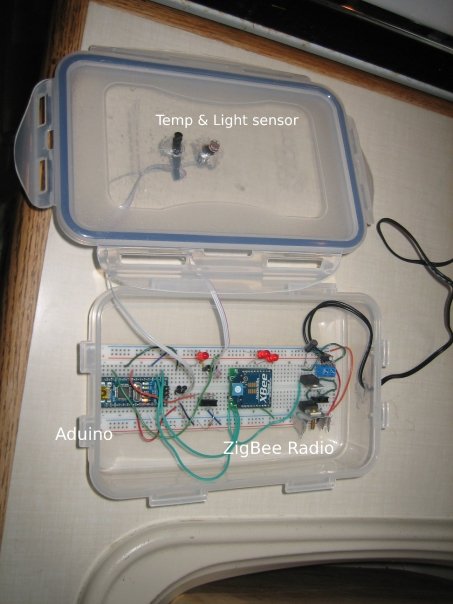
Here is a view showing the layout of the components when it was using my Arduino Nano:


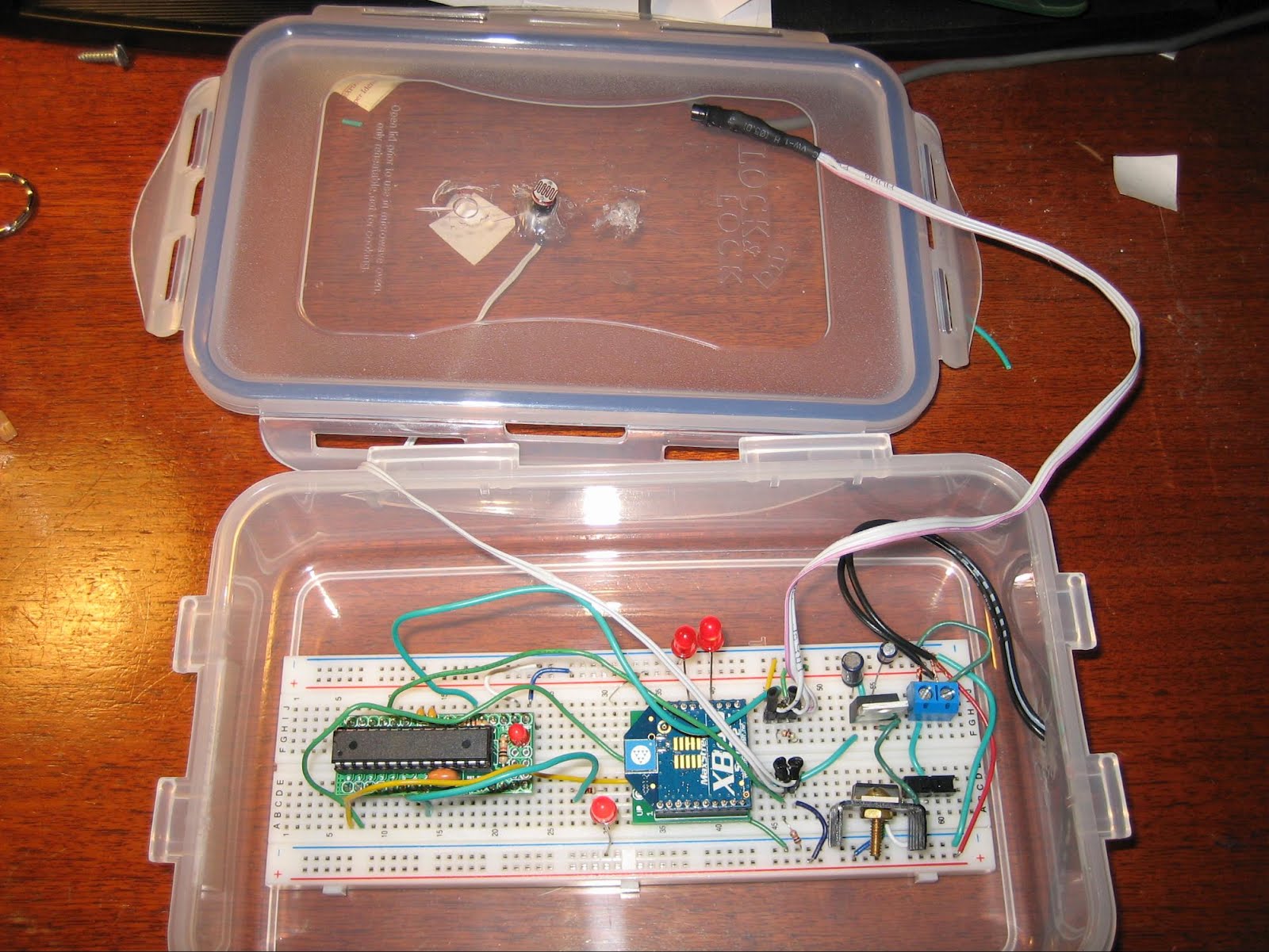
And here is a more resent shot showing it with my new DuinoStamp installed:


Good heavens I do sloppy breadboard installations! The plastic food container idea comes from Tom Igoe's excellent Making Things Talk, which is definitely the first book to buy if you are interested in this stuff. The box is reasonably weatherpoof and I have had this running outdoors for quite a while with no problems.

The firmware for the remote is reasonably simple, it checks the state of the two sensors (three if the moisture detector is installed) and the values received via the Xbee serial link. If a "g" character (ASCII 103) then the Arduino pushes out the values of the sensors and the state of the two on-board LEDs out over the Xbee. If an "h" is received (ASCII 104) then the Arduino turns on LED 2 connected to digital pin 7. If an "l" is received (ASCII 108) then the LED is turned off.

For those who absolutely have to see the source code, it is posted here. There is a lot of material related to the OneWire digital temp sensor that, frankly, I don't understand, but I borrowed from here.

That should be enough for now. Next up will be the Gumstix webserver & data logger.