Showing posts with label Xbee. Show all posts

Wednesday, October 23, 2013

Resurecting the Arduino/Xbee/Gumstix sensor network

About four years ago, I built a simple sensor network that used a couple of Arduinos, a Gumstix Linux mini computer and Xbee wireless that acted as an indoor-outdoor temperature display. A couple of years back, the outdoor part of the system stopped working. I poked it and prodded it and finally just decided the Arduino clone I was using had died.

Finally, after it had sat on my shelf for a couple of years, I figured I should start to look at salvaging some of the parts for something new. Just as a last chance, I once again unplugged the processor and juggled the wires and suddenly, it works like a charm!! As with most thing, the threat of imminent destruction got it moving!

Anyway, in honour of it's miraculous recovery, I have fixed up my blog posts and reinserted the graphics Google lost for me. The posts can be found at:

  1. Overview of the sensor network
  2. Indoor Outdoor temp display
  3. Xbee -Gumstix hardware
  4. Gumstix-Arduino software

This project is pretty old now and obviously could be done much more easily with newer models of Arduino like the Yun, but it does show some good basics on getting Zigbee and PHP and Arduino all working together. Apparently, too, it is capable of great longevity!

Wednesday, January 28, 2009

Gumstix-Xbee Modem Hardware

Hola Amigos!

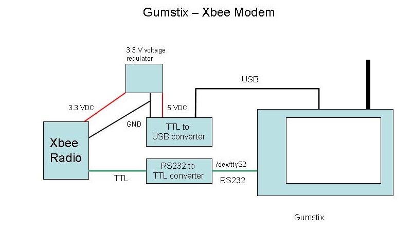
Now to continue with documenting the Remote Sensor rig, this section will describe the physical hardware that is used to interface the Gumstix server via Xbee to the Remote Sensor box and the Indoor-Outdoor Temperature display described earlier. I will discuss the PHP scripts running on the Gumstix in a later post.

The astute observer will note that this circuit is actually rather silly. Why is there an RS232-TTL converter and a USB-TTL converter? The answer is that the Gumstix does not at this point support the FTDI USB-Serial chip, but I needed something to power the circuit so I could avoid having an extra wall-wart in the picture. So, a very good DLP USB converter (Digi-key part 813-1018-ND) is essentially being totally wasted. I did try just pulling the power directly off a USB connector, but it didn't seem to be sufficient to run the Xbee, so the DLP Converter is obviously doing some sort of power conditioning along the way.


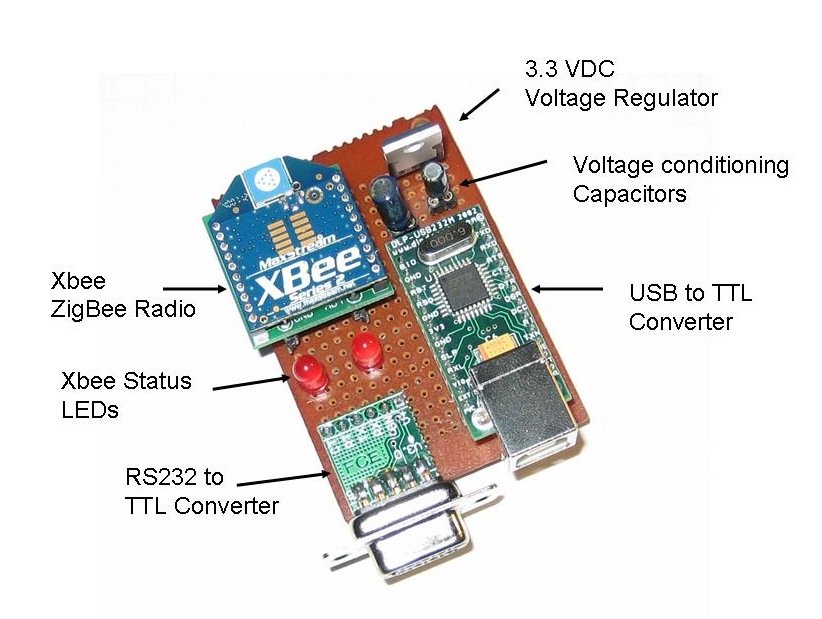
This shows the layout of the board. Very neat! This actually uses the Sparkfun Xbee breakout board (Sparkfun part number BOB-08276) which just provides a simple breakout for the Xbee pins rather than the complete power package on the Lady Ada carrier board I used on the Indoor-Outdoor Temperature Display. There is no design reason for this. I just happened to build this unit before I had discovered the Lady Ada breakout board. This is why I needed to put in a separate 3.3 VDC voltage regulator and the two power conditioning capacitors.

There is a 10 uF capacitor on the 5 VDC input of the regulator and a 1 uF on the 3.3 VDC output. I ain't no expert on this stuff, but what I understand is if they ain't there it ain't workin'.


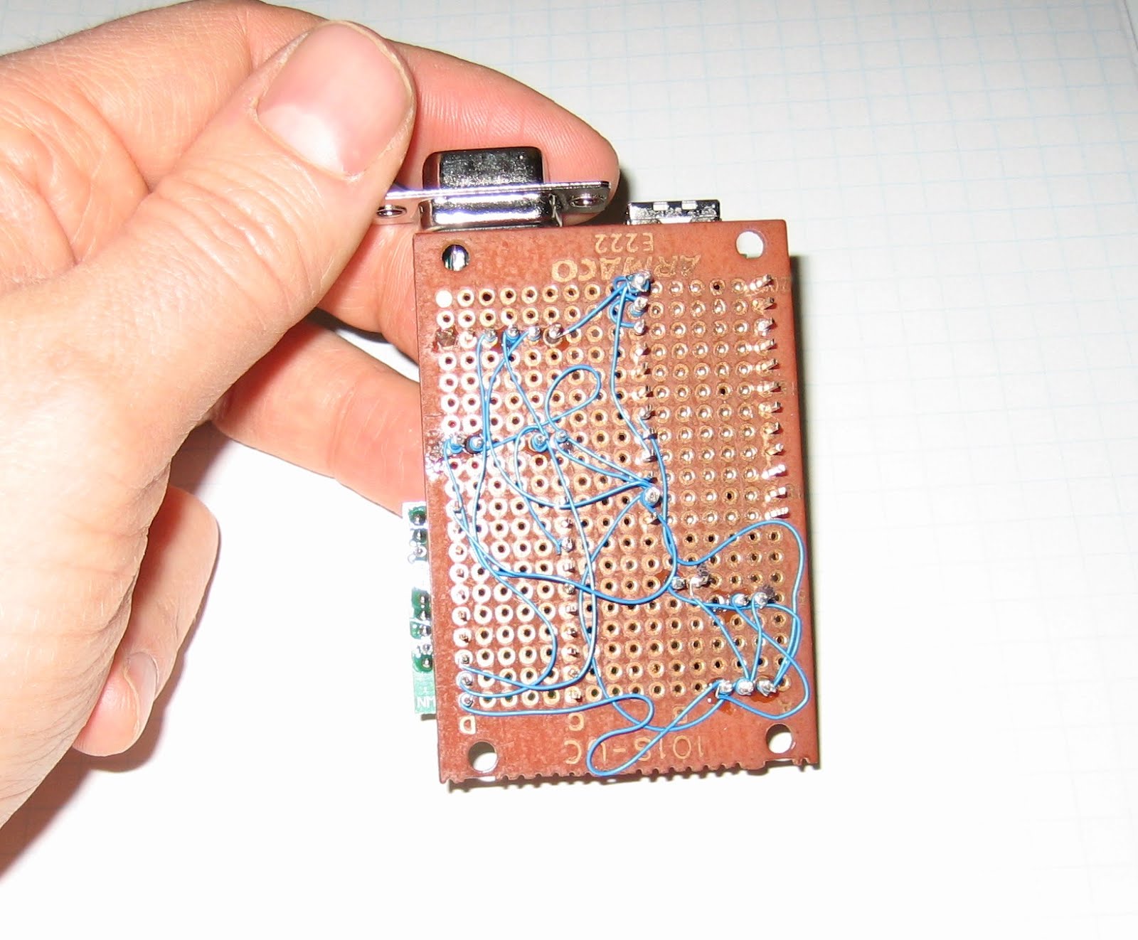
Again, this circuit is built using wire wrap, which provides a quick way to make a reasonably permanent circuit. I should be good and color code the power, ground and data wires and arrange them all more neatly, but I'm sure that will come with practise.

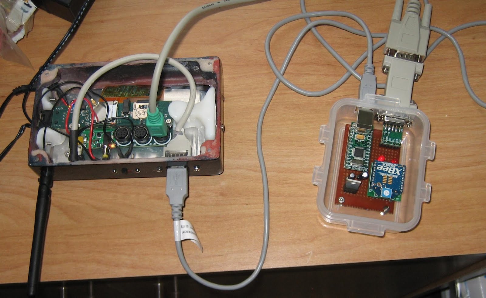
And here is the completed unit in the inevitable plastic food container. The Gumstix case is my own design (described here). The RS232 comes off of the Gumstix LCD-Serial board and through a gender changer to the RS232-TTL converter. The USB connects to the USB on the converter. The Arduino units communicated with the Xbee on this and the Gumstix then communicates over Wi-Fi to my home network.


Next post, I will describe the software that runs everything!

Monday, January 12, 2009

My Arduino Sensor Network

Alright, now has come the time to start discussing the meat of my development projects, which is a very simple sensor network linked via Zigbee radio. In itself, this isn't really terribly useful. All it does is record outside temperature and light levels and then display them with a serial-LCD display by my desk. You could do most of this with a simple wireless indoor-outdoor thermometer from Canadian Tire! However, what I am really building towards is building the control system for a solar pool heater for next summer's pool season so I don't have to faint from hypothermia every time I go for a swim.

Here is a diagram of the current system:

The three components are - each will be discussed in their own posts:

  • Gumstix webserver & data logger - This uses a Gumstix Linux box and a simple RS232 link to talk to an Xbee Zigbee radio from Digi (formerly Maxstream). Click here for more info on the radios.
  • Indoor display & indoor temp sensor - This displays the indoor temp from a local sensor and the outdoor temp from the remote.
  • Remote light & temp sensor - I will discuss this in more detail next.

Remote Sensor unit:

This is probably the most critical unit. It contains:
  • A DS1820 OneWire precision temperature sensor
  • A photoresistor light sensor
  • The on-bard Arduino LED connected to digital pin 13 shows whether the light level has crossed a threshold
  • The other LED is to test sending commands over the Xbee
  • It can optionally have a moisture detector, but I have taken this out for now
  • Power regulators for 5 VDC (for the Arduino) and 3.3 VDC for the Xbee
Here is a rather idiosyncratic schematic (click to see full size):


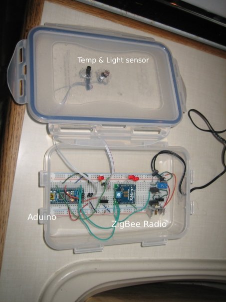
Here is a view showing the layout of the components when it was using my Arduino Nano:


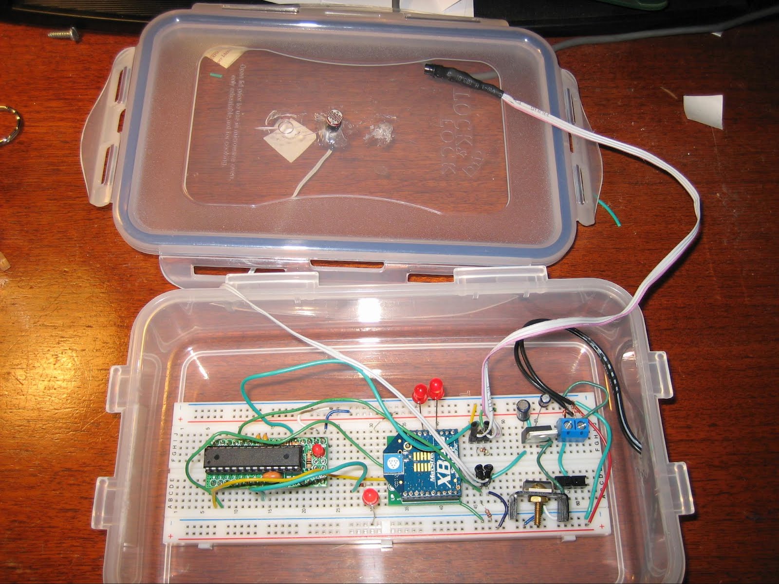
And here is a more resent shot showing it with my new DuinoStamp installed:


Good heavens I do sloppy breadboard installations! The plastic food container idea comes from Tom Igoe's excellent Making Things Talk, which is definitely the first book to buy if you are interested in this stuff. The box is reasonably weatherpoof and I have had this running outdoors for quite a while with no problems.

The firmware for the remote is reasonably simple, it checks the state of the two sensors (three if the moisture detector is installed) and the values received via the Xbee serial link. If a "g" character (ASCII 103) then the Arduino pushes out the values of the sensors and the state of the two on-board LEDs out over the Xbee. If an "h" is received (ASCII 104) then the Arduino turns on LED 2 connected to digital pin 7. If an "l" is received (ASCII 108) then the LED is turned off.

For those who absolutely have to see the source code, it is posted here. There is a lot of material related to the OneWire digital temp sensor that, frankly, I don't understand, but I borrowed from here.

That should be enough for now. Next up will be the Gumstix webserver & data logger.