Showing posts with label wire wrap. Show all posts

Friday, June 6, 2014

Wire Wrap Introduction Video

This post is to provide a link to my new video on YouTube and a bit more accompanying explanation.

First off, here is the video:


For those who are curious about some further explanation of the process and purchasing wire wrap supplies, I see that Jameco has a great online article and carries the supplies.(Check it out here). Wikipedia also has a great article on wire wrapping here.

I recall working for a company in the 1990s that was still using it extensively for building aircraft maintenance simulators because it is reliable, quick and easy and well suited to very small production run products. Early computers used the technique extensively. Check out this picture of a Z80 backplane from 1977:


The main challenge is obviously keeping track of the many point-to-point connections when you are looking at the back of the board! I seem to recall the firm I worked for had some sort of system of tables for keeping track of what went from where to where. Generally, I find that if I am going to have problems with a wire wrap assembly, it will be an error I have made in losing track of which pin is which when I flip the board over!

That's it for now! Soon I will do a longer post on my first work with the nRF24L01 radios and my DigiX board. I have something almost working and when it's done I will provide more details.


Wednesday, January 28, 2009

Gumstix-Xbee Modem Hardware

Hola Amigos!

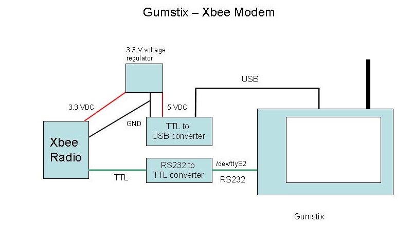
Now to continue with documenting the Remote Sensor rig, this section will describe the physical hardware that is used to interface the Gumstix server via Xbee to the Remote Sensor box and the Indoor-Outdoor Temperature display described earlier. I will discuss the PHP scripts running on the Gumstix in a later post.

The astute observer will note that this circuit is actually rather silly. Why is there an RS232-TTL converter and a USB-TTL converter? The answer is that the Gumstix does not at this point support the FTDI USB-Serial chip, but I needed something to power the circuit so I could avoid having an extra wall-wart in the picture. So, a very good DLP USB converter (Digi-key part 813-1018-ND) is essentially being totally wasted. I did try just pulling the power directly off a USB connector, but it didn't seem to be sufficient to run the Xbee, so the DLP Converter is obviously doing some sort of power conditioning along the way.


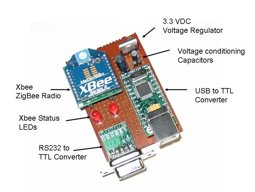
This shows the layout of the board. Very neat! This actually uses the Sparkfun Xbee breakout board (Sparkfun part number BOB-08276) which just provides a simple breakout for the Xbee pins rather than the complete power package on the Lady Ada carrier board I used on the Indoor-Outdoor Temperature Display. There is no design reason for this. I just happened to build this unit before I had discovered the Lady Ada breakout board. This is why I needed to put in a separate 3.3 VDC voltage regulator and the two power conditioning capacitors.

There is a 10 uF capacitor on the 5 VDC input of the regulator and a 1 uF on the 3.3 VDC output. I ain't no expert on this stuff, but what I understand is if they ain't there it ain't workin'.


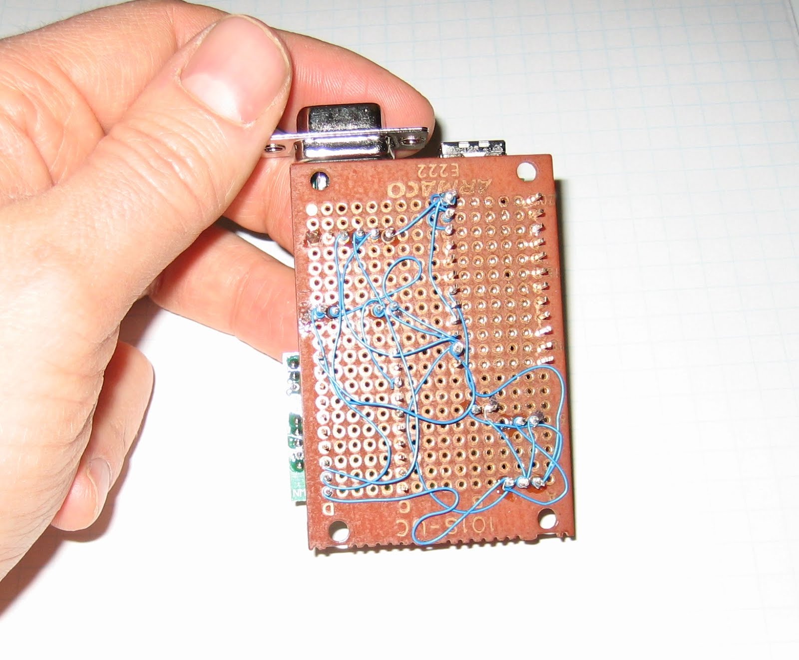
Again, this circuit is built using wire wrap, which provides a quick way to make a reasonably permanent circuit. I should be good and color code the power, ground and data wires and arrange them all more neatly, but I'm sure that will come with practise.

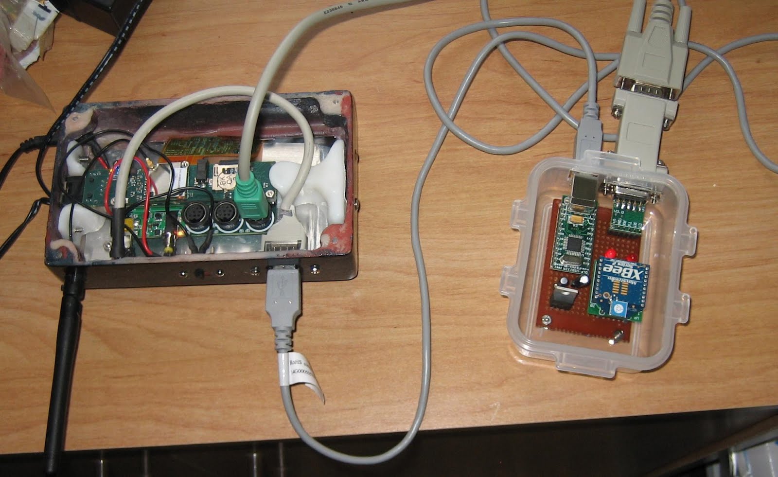
And here is the completed unit in the inevitable plastic food container. The Gumstix case is my own design (described here). The RS232 comes off of the Gumstix LCD-Serial board and through a gender changer to the RS232-TTL converter. The USB connects to the USB on the converter. The Arduino units communicated with the Xbee on this and the Gumstix then communicates over Wi-Fi to my home network.


Next post, I will describe the software that runs everything!