As mentioned in the previous post, I have bought a plasma cutter a short while ago from the good folks at http://www.plasmametalcutter.com/. Since I only have 110 service in the garage, I had to opt for the Cut40D model (which is confusingly called the Slice40D on the face of the unit). This model features auto-switching between 110 and 220. It comes with a 220 plug on the end, but it is easy enough to switch it for a 110 style plug. I opted for the 110 20 AMP style plug.
All in all, it is a very good study unit. It slices through sheet metal like it isn't even there and so far does fine up to at least 1/4" mild steel. I haven't yet tried it out on thicker stock, but I'm not sure if it could go to a full 1/2" or not. Most of my projects are with 1/8" angle iron stock and it blasts through that with no problem. Like welding, you need to watch the safety precautions and it takes some practise to make steady cuts - especially straight lines.
The Gianttech folks I bought the unit off of were very helpful, however shipping up here to Canada took quite a while, but as a hobbyist I wasn't in a huge hurry. I also bought the package of extra consumables available for the unit since I read that these can be used up quickly. I have had to change the tip once, but I think that is because I fried it when I was learning how to use the unit. Now that I have more practise, I am not noticing much deterioration of the tip or other consumables.
I also had to upgrade my air compressor to an 8 gallon 2+ HP unit. I ended up buy this unit from Boss Tools. It is a very sturdy compressor that seems to deliver loads of pressure! While the Cut40D comes with a combination air regulator and filter, on the advice of my welding teacher, I also added in an extra filter (this item). Apparently, the drier and cleaner the air, the better the cutting and the longer the consumables will last.
Here is a quick video of the cutter in action (note that I keep calling it the "Slice40D" since that is what the face of the unit says):
I only had a couple of small issues with the unit. Like many Chinese tools, the manual was laughably short. My Lincoln Electric MIG welder came with an encyclopedia compared to the Gianttech cutter! However, what was there was adequate to get started.
Another issue was that I initially got a lot of air leakage from the hoses connecting the regulator/filter unit to the cutter. First, I replaced the hose clamps and that mostly fixed it, then I replaced the 1/4" NPT-hose barb fitting off of the regulator and that fixed it. Again, pretty small stuff, and I suppose typical of the small "fit and finish" items you find on Chinese tools (my lathe & milling machine also needed minor tweaks). For the money, I am frankly amazed with how well it works. If I were running a full welding shop, I would probably opt for a heavy duty Miller machine or something, but for a "weekend warrior" hobbyist like me it works great!
Monday, December 14, 2009
Plasma Cutting Table
Plasma Cutting Table
Maintaining my blistering pace of a posting every month or so, here is another project write-up along the metal working lines. I recently bought a Gianttech plasma cutter from the good people at http://www.plasmametalcutter.com (which I will post about shortly). It became obvious pretty quickly that just cutting things on the edge of the welding table wouldn't work very well - and risked damaging my beautiful 3/16 steel top for the welding table. So, the answer was to build a simple plasma cutting table.
At it's most basic, a plasma cutting table is just a set of steel slats turned on their end that conduct electricity to the workpiece, but won't interfere with the cutting action because of their thin profile. I decided that the most reasonable design was to go for 1 1/5" slats of 1/8" thick mild steel. I also figured that the grating part of the table would take a lot of abuse from cutting so it would be good to make it so it could be easily turned over and eventually replaced. The basic idea then was to build the grate as one unit, then have it be able to be set onto the base frame to make the completed table. The base frame is made from good ol' 1 1/2" x 1/8" angle iron. The table surface area is 2' x 2'.

The first parts that I made (which I didn't take pictures of) were two angle iron squares. One makes up the top frame and the other is the cross brace for the legs.
Here is the construction process for the grate - I just used corner clamps to keep adding in more and more slats. They are positioned just slightly over 1 1/2" apart so they space out evenly:

When it was done - and with a bit of grinding and fitting - the grate fit perfectly into the top frame:
Here are the grate, squares and legs waiting for assembly:

...and here is the completed unit:

Ah, the astute observer will notice, why isn't the grate nestled neatly in the top frame the way it was designed? Because i managed to weld it together upside down! Arrgghh! Another lesson that WELDING IS PERMANENT! Double check everything before reaching for the welding gun. However, I was able to weld some extra angle iron onto the top frame to hold the grate. So, it ends up being an inch or so higher than I might have liked, but otherwise is very usable and the top is still easily replaceable:

It's all stores up nice and compact and when I need to work, I can just swing the welder and cutter out on their trolley.
Maintaining my blistering pace of a posting every month or so, here is another project write-up along the metal working lines. I recently bought a Gianttech plasma cutter from the good people at http://www.plasmametalcutter.com (which I will post about shortly). It became obvious pretty quickly that just cutting things on the edge of the welding table wouldn't work very well - and risked damaging my beautiful 3/16 steel top for the welding table. So, the answer was to build a simple plasma cutting table.
At it's most basic, a plasma cutting table is just a set of steel slats turned on their end that conduct electricity to the workpiece, but won't interfere with the cutting action because of their thin profile. I decided that the most reasonable design was to go for 1 1/5" slats of 1/8" thick mild steel. I also figured that the grating part of the table would take a lot of abuse from cutting so it would be good to make it so it could be easily turned over and eventually replaced. The basic idea then was to build the grate as one unit, then have it be able to be set onto the base frame to make the completed table. The base frame is made from good ol' 1 1/2" x 1/8" angle iron. The table surface area is 2' x 2'.

The first parts that I made (which I didn't take pictures of) were two angle iron squares. One makes up the top frame and the other is the cross brace for the legs.
Here is the construction process for the grate - I just used corner clamps to keep adding in more and more slats. They are positioned just slightly over 1 1/2" apart so they space out evenly:

When it was done - and with a bit of grinding and fitting - the grate fit perfectly into the top frame:
Here are the grate, squares and legs waiting for assembly:

...and here is the completed unit:

Ah, the astute observer will notice, why isn't the grate nestled neatly in the top frame the way it was designed? Because i managed to weld it together upside down! Arrgghh! Another lesson that WELDING IS PERMANENT! Double check everything before reaching for the welding gun. However, I was able to weld some extra angle iron onto the top frame to hold the grate. So, it ends up being an inch or so higher than I might have liked, but otherwise is very usable and the top is still easily replaceable:

Monday, November 16, 2009
My Welding Cart
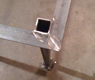
Having finished up my welding table, the next step was to have something to actually put my welder on rather than having it sit on the floor. So, I built the following which is based on a plan from "Welding Complete" from Creative Publishing International (available from Amazon here). However, I needed to modify the original plan to make it a bit wider so my plasma cutter would have a place to stay.
Here is the drawing- which omits the wheels which were just purchased from the local home center:

I won't bother going through all the build since it was basically the same as the welding table, but one thing I forgot to get a picture of was the correct way to align the upright components for welding, which is like this:

Use a carpenter's square to ensure the uprights are at a perfect 90 degrees before welding! I missed this crucial step with one of the legs on my welding table and it will be ever so slightly out of square forever now. Welding is definitely a measure THREE times, cut once, measure TWO MORE TIMES then weld type of process.
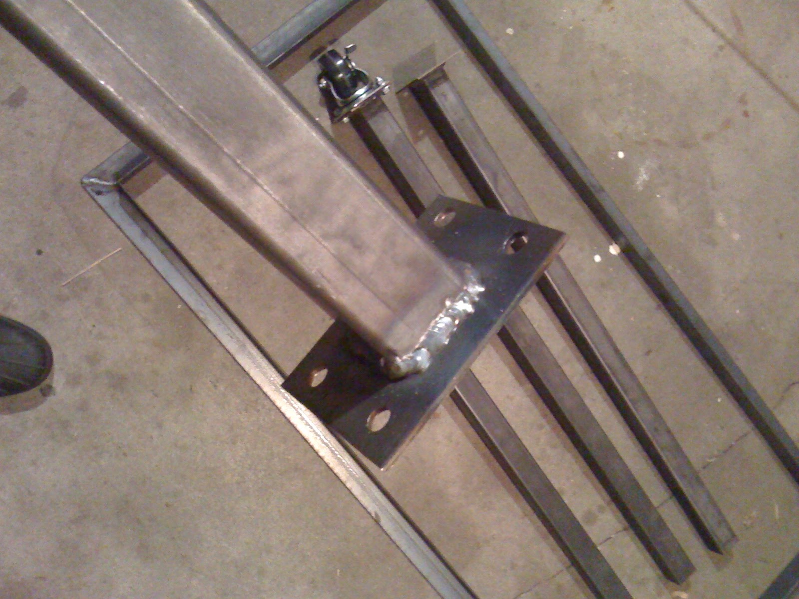
Here is the whole frame before painting. The hooks are to hang cables off of, but I am a bit worried I will be catching my knees on them.

Finally, a good thick coat of tractor green paint covers a multitude of sins! Actually, we have a pool pump in the same garage as the welding gear and occasionally small amounts of chlorine gas seep out and rust steel instantly, so I really need to paint everything to preserve it. I also put the rubber matting on the help protect the finish and provide some extra electrical insulation.

Here is the whole team! Note that the welding cart is extra wide so the plasma cutter can go beside it.

Next up... Bringing some order to my chaotic garage and workshop, which is hardly a project worth blogging about! I will be welding up some shelves and cabinets as part of the process and I will post that later. I also promise to get back to the Arduino soon. I have another Ethernet shield I haven't yet got assembled and I really want to look at networking two Arduinos together and having them do something halfway useful!
Here is the drawing- which omits the wheels which were just purchased from the local home center:


Use a carpenter's square to ensure the uprights are at a perfect 90 degrees before welding! I missed this crucial step with one of the legs on my welding table and it will be ever so slightly out of square forever now. Welding is definitely a measure THREE times, cut once, measure TWO MORE TIMES then weld type of process.
Here is the whole frame before painting. The hooks are to hang cables off of, but I am a bit worried I will be catching my knees on them.

Finally, a good thick coat of tractor green paint covers a multitude of sins! Actually, we have a pool pump in the same garage as the welding gear and occasionally small amounts of chlorine gas seep out and rust steel instantly, so I really need to paint everything to preserve it. I also put the rubber matting on the help protect the finish and provide some extra electrical insulation.

Here is the whole team! Note that the welding cart is extra wide so the plasma cutter can go beside it.

Next up... Bringing some order to my chaotic garage and workshop, which is hardly a project worth blogging about! I will be welding up some shelves and cabinets as part of the process and I will post that later. I also promise to get back to the Arduino soon. I have another Ethernet shield I haven't yet got assembled and I really want to look at networking two Arduinos together and having them do something halfway useful!
Thursday, November 5, 2009
Welding Table Construction
In honour of Monty Python's 40th Anniversary... And now for something completely different!
I believe way back in the original start of the blog, I explained that I also did a lot of machining including designing & building steam engines a few years ago. I had always meant to take a welding course, and on a whim I decided to finally do that this fall. So, the last few Saturdays I have been struggling out of bed at 6:30 AM to get into to weld with a huge stick welder (Shielded Metal Arc Welding - SWAM) process. Naturally, I have gotten totally obsessed and decided to get a welder for myself!
Originally, I wanted to get a 240 VAC stick welder, but my friendly neighborhood electrician told me the garage wiring just wasn't up to it, and this is hardly something I want to do inside the house! After some research, I settled on a Lincoln Electric MIG-Pak 140 unit which runs off of regular 120 VAC (similar to this) that does Metal Inert Gas arc welding (aka GMAW - Gas-shielded Metal Arc Welding). Fortuitously, it went on a good sale and I picked up a bottle of C02/Argon shielding gas, a leather welders coat and an auto-darkening welding helmet and I was set!
The technique and setup for the MIG welding is quite different from the big Hobart industrial units I am using in class, but MIG welding is pretty easy to at least pick up the basics of. The good thing with getting used to using the big welder in class is it gives you a very healthy respect for all the safety precautions and you get all the good theory on how everything is supposed to work and the various types of welds as well as the good advice of an experienced instructor.
So, after fooling around with my welder to get a feel for how it performs with various thicknesses of metal and so on, I decided the first traditional project for a starting welder is to build a metal welding table. I need the extra surface space in the shop and I definitely need a metal surface table for arc welding.
Step 1 - I worked up a design to get the rough dimensions and the shopping list for the metal store:

This used 1 1/2 inch square tubing for the legs, 1 1/2 angle iron for the frame and 3/16 thick sheet for the table top.
Step 2 - I bought the table top already cut to size and then cut down the frame and leg pieces from the ten foot lengths I bought. Here are the parts laid out before welding:

Step 2 - First I welded the frame that supports the top. The parts were cut mitered and then I put them on some firebricks on the top itself - on the assumption that the top is more level that the old floor of my garage!

Step 3 - With the top frame done, then I welded the plates for the caster wheels to the bottom of the legs:

Not too bad MIG welds considering I am just starting out!

Step 4 - I welded the leg assemblies to the frame assemblies. I wish I had captured the proper way of lining up the legs perfectly perpendicular to the frame! I actually messed up the first leg and it went on slightly out of true, but the other three legs went on perfectly. You will see later that it's not too bad and the one leg being slightly out won't be too big an impact. Once the legs are welded onto the frame, I needed to grind down the welds on the top of the frame so it would mate properly to the table top:
Step 5 - The frame and leg assembly was welded to the top. Here I use an intermittent rather than a continuous weld:

Step 6 - Roll it out of the shop and paint it! The slats are 1 1/2 inch wide 1/8 thick strapping I added to make a shelf for storing stock and other bits & pieces. Can you tell which leg is slightly out of alignment?

Here it is with good double coat of primer:

Finally, it got a good heavy coat of Tremclad basic green glossy paint so it looks like a tractor!

A nice substantial first welding project and something very useful for the shop! Next up will be a cart to put the welder on and my new plasma cutter which I should get next week.
Some day, I will combine the Arduino, welding and maching stuff into one project, promise!
I believe way back in the original start of the blog, I explained that I also did a lot of machining including designing & building steam engines a few years ago. I had always meant to take a welding course, and on a whim I decided to finally do that this fall. So, the last few Saturdays I have been struggling out of bed at 6:30 AM to get into to weld with a huge stick welder (Shielded Metal Arc Welding - SWAM) process. Naturally, I have gotten totally obsessed and decided to get a welder for myself!
Originally, I wanted to get a 240 VAC stick welder, but my friendly neighborhood electrician told me the garage wiring just wasn't up to it, and this is hardly something I want to do inside the house! After some research, I settled on a Lincoln Electric MIG-Pak 140 unit which runs off of regular 120 VAC (similar to this) that does Metal Inert Gas arc welding (aka GMAW - Gas-shielded Metal Arc Welding). Fortuitously, it went on a good sale and I picked up a bottle of C02/Argon shielding gas, a leather welders coat and an auto-darkening welding helmet and I was set!
The technique and setup for the MIG welding is quite different from the big Hobart industrial units I am using in class, but MIG welding is pretty easy to at least pick up the basics of. The good thing with getting used to using the big welder in class is it gives you a very healthy respect for all the safety precautions and you get all the good theory on how everything is supposed to work and the various types of welds as well as the good advice of an experienced instructor.
So, after fooling around with my welder to get a feel for how it performs with various thicknesses of metal and so on, I decided the first traditional project for a starting welder is to build a metal welding table. I need the extra surface space in the shop and I definitely need a metal surface table for arc welding.
Step 1 - I worked up a design to get the rough dimensions and the shopping list for the metal store:

This used 1 1/2 inch square tubing for the legs, 1 1/2 angle iron for the frame and 3/16 thick sheet for the table top.
Step 2 - I bought the table top already cut to size and then cut down the frame and leg pieces from the ten foot lengths I bought. Here are the parts laid out before welding:

Step 2 - First I welded the frame that supports the top. The parts were cut mitered and then I put them on some firebricks on the top itself - on the assumption that the top is more level that the old floor of my garage!

Step 3 - With the top frame done, then I welded the plates for the caster wheels to the bottom of the legs:

Not too bad MIG welds considering I am just starting out!
Step 4 - I welded the leg assemblies to the frame assemblies. I wish I had captured the proper way of lining up the legs perfectly perpendicular to the frame! I actually messed up the first leg and it went on slightly out of true, but the other three legs went on perfectly. You will see later that it's not too bad and the one leg being slightly out won't be too big an impact. Once the legs are welded onto the frame, I needed to grind down the welds on the top of the frame so it would mate properly to the table top:

Step 5 - The frame and leg assembly was welded to the top. Here I use an intermittent rather than a continuous weld:

Step 6 - Roll it out of the shop and paint it! The slats are 1 1/2 inch wide 1/8 thick strapping I added to make a shelf for storing stock and other bits & pieces. Can you tell which leg is slightly out of alignment?

Here it is with good double coat of primer:

Finally, it got a good heavy coat of Tremclad basic green glossy paint so it looks like a tractor!

A nice substantial first welding project and something very useful for the shop! Next up will be a cart to put the welder on and my new plasma cutter which I should get next week.
Some day, I will combine the Arduino, welding and maching stuff into one project, promise!
Tuesday, September 8, 2009
Further on the POP3 email checker
Well, since this project has been a bit of a surpirse hit, I thought I would include a few further notes and refinements.
This is a small change to the updateClient function that just flashes the LED rapidly four times to indicate the network is down:
What is odd is that when I have tried this with another LED it blinks very dimly - even when I move around which digital pin the other LED is coming from. Very odd and I still haven't figured out what is causing that.
Another thing to watch for is that this assumes that the number of emails comes through in array position 106 & 107 (I then subtract 48 to make the ASCII code into an integer):
This, of course, may vary depending on how many characters there are in your POP3 server name and so on. I would recommend starting with the basic commands for getting the POP3 string back:
Then watching the output in the serial window, which will look something like:
You can then use this output to figure out the right position in the array for mailNum1 & mailNum2.
Hope that helps someone out there. It has been very flattering to see how many folks are interested in building this for themselves. As I explained in the first post, once you have the raw number of emails as an integer you can process with Arduino, you can do all sorts of interesting things beyond just flashing and LED!
This is a small change to the updateClient function that just flashes the LED rapidly four times to indicate the network is down:
void updateClient() //This function contacts the POP3 server
{
  if ((millis() - updateTimer) > 5000)
  {
    Ethernet.begin(mac, ip);
//    Serial.println("connecting...");
    delay(1000);
    if (client.connect())
    {
//    Serial.println("connected");
    client.println("user Pop.User"); //Insert your usual email login name
    client.println("pass YourPassword"); //And your password here
    client.println("quit");
    client.println();
    clientConnected = true;
    }
    else
    {
//    Serial.println("connection failed");
// Flash four time rapidly to indicate network down.
      for (int x = 0; x < 4; x++){
              digitalWrite(ledPin, HIGH);
              delay(100);
              digitalWrite(ledPin, LOW);
              delay(100);
      }
    }
    updateTimer = millis();
  }
}
What is odd is that when I have tried this with another LED it blinks very dimly - even when I move around which digital pin the other LED is coming from. Very odd and I still haven't figured out what is causing that.
Another thing to watch for is that this assumes that the number of emails comes through in array position 106 & 107 (I then subtract 48 to make the ASCII code into an integer):
          mailNum1 = inString[106] - 48; //Array position 106 contains the first digit
          mailNum2 = inString[107] - 48; //Array position 107 contains the 2nd digit if it is available
This, of course, may vary depending on how many characters there are in your POP3 server name and so on. I would recommend starting with the basic commands for getting the POP3 string back:
#include <Ethernet.h>

byte mac[] = { 0xDE, 0xAD, 0xBE, 0xEF, 0xFE, 0xED };
byte ip[] = { 192,168,0,172 };
byte server[] = { XXX, XXX, XXX, XXX }; // IP address of your POP3 server

Client client(server, 110);

long updateTimer;
boolean clientConnected = false;

void setup()
{
 Serial.begin(9600);
}

void loop()
{
 updateClient();
 checkAvail();
}

void updateClient()
{
 if ((millis() - updateTimer) > 10000)
 {
   Ethernet.begin(mac, ip);
   Serial.println("connecting...");
   delay(1000);
   if (client.connect())
   {
 Serial.println("connected");
 client.println("user user.name"); //Insert your usual email login name
 client.println("pass YourEmailPassword"); //And your password here
 client.println("quit");
 client.println();
 clientConnected = true;
   }
   else
   {
 Serial.println("connection failed");
   }
   updateTimer = millis();
 }
}

void checkAvail()
{
 if (clientConnected)
 {
   if (client.available())
   {
 char c = client.read();
 Serial.print(c);
   }
   if (!client.connected())
   {
 Serial.println();
 Serial.println("disconnecting.");
 client.stop();
 clientConnected = false;
   }
 }
}
Then watching the output in the serial window, which will look something like:
connecting...
connected
+OK hello from popgate 2.43 on pop108.xxx.xxx.xxx.xxx.xxx
+OK password required.
+OK maildrop ready, 0 messages (0 octets) (16335883)
+OK server signing off.

disconnecting.
You can then use this output to figure out the right position in the array for mailNum1 & mailNum2.
Hope that helps someone out there. It has been very flattering to see how many folks are interested in building this for themselves. As I explained in the first post, once you have the raw number of emails as an integer you can process with Arduino, you can do all sorts of interesting things beyond just flashing and LED!
Thursday, September 3, 2009
Arduino POP3 Email Checker
Since it turns out people actually occasionally READ this blog, I decided it was time to go back to do an Arduino project and try something different. Since I hadn't done any Arduino work with the Internet before, I decided to try something I thought would be relatively simple - having the Arduino check my email and give me some sort of visual indication of how many emails I have. I started out with:
Both were bought from the good people at Robotshop.ca.

These are just combined with a high intensity LED - which really should have a resistor and will have one eventually!

Here is a quick video - sorry it is a bit murky and the LED is a bit bright!
This was actually probably the hardest Arduino code I ever wrote! For one thing, I hadn't done anything substantial with the Arduino for a while and I found I had forgotten much of what I thought I knew. Also, getting the timing right and getting the number of emails out of the return string actually proved pretty difficult. I made things more difficult for myself by trying to use the String library (formerly TextString), which for some reason didn't return consistent results and was generally not documented and finicky. Then I found the usual LED 13 wouldn't work properly - perhaps because the Ethernet Shield was interfering with it. All-in-all, this small program must have taken me three weeks to write!
I did have a bit of help with the code from Digger450 on the Arduino forum in this exchange, which I am very grateful for!
However, now that it is done, this is a nice little demo of Ardunio on the Internet that does do something at least semi-useful. My next extension may be to hook it up to a servo so that it shows my emails on a physical chart or something. I could also use my SparkFun SerialLCD unit to display the subject lines or something.
Here is the source code:
/*=================================================
Ethernet POP3 Mail Checker & indicator

Checks how many messages are waiting on the POP 3 server
and flashed LED on Pin 9 to indicate number of messages.

It will handle up to 99 messages in the POP3 mailbox.

Uncomment the serial lines for troubleshooting.

Copyright by Chris Armour
3 September 2009
http://opensourceprojects-torchris.blogspot.com/

===================================================*/

#include <Ethernet.h>

byte mac[] = { 0xDE, 0xAD, 0xBE, 0xEF, 0xFE, 0xED };
byte ip[] = { 192,168,0,167 }; // IP address you wish to assign to Arduino
byte server[] = { XXX, XXX, XXX, XXX }; // IP address of your POP3 server
char inString[165]; // Number of characters to be collected
int i = 0;
int mailNum1 = 0; // First digit of the email number
int mailNum2 = 0; // Second digit
int mailTotal = 0; // Total # of messsage
char d;
int ledPin = 9;

Client client(server, 110); //The default POP port is 110

long updateTimer;
boolean clientConnected = false;

void setup()
{
//  Serial.begin(9600);
pinMode(ledPin, OUTPUT);
digitalWrite(ledPin, LOW);
}

void loop()
{

updateClient();
d = checkAvail();
if (d >= 10){
getMailNum();
}

}

/*========================================
        Functions
=========================================*/

void updateClient() //This function contacts the POP3 server
{
if ((millis() - updateTimer) > 5000)
{
 Ethernet.begin(mac, ip);
//    Serial.println("connecting...");
 delay(1000);
 if (client.connect())
 {
//    Serial.println("connected");
 client.println("user Your.Name"); //Insert your usual email login name
 client.println("pass PassWord"); //And your password here
 client.println("quit");
 client.println();
 clientConnected = true;
 }
 else
 {
//    Serial.println("connection failed");
 }
 updateTimer = millis();
}
}

char checkAvail() //This checks if there is data available and returns a char
{
if (clientConnected)
{
 if (client.available())
 {
 char c = client.read();
     return(c);
 }
 if (!client.connected())
 {
//    Serial.println();
//    Serial.println("disconnecting.");
 client.stop();
 clientConnected = false;
 }
}
}

int getMailNum() //This actually loads the char returned by checkAvail() and puts in into an array
{
inString[i] = d;
i++;
if (i == 165){
   i = 0;
       client.flush();
       mailNum1 = inString[106] - 48; //Array position 106 contains the first digit
       mailNum2 = inString[107] - 48; //Array position 107 contains the 2nd digit if it is available
       if ((mailNum2 >= 0) && (mailNum2 <= 9)){ //If mailNum2 is present, then it is a two digit mail count
         mailTotal = (mailNum1 * 10) + mailNum2; //when 2 digits are present, multiply the 1st by 10 then add to mailTotal
//            Serial.print("Total emails:  ");
//            Serial.println(mailTotal);
          blinkLED(); //Run the blink function as many times as there are emails
       }
       else {
         if ((mailNum1 >= 0) && (mailNum1 <= 9)){//if there is only one digit, then that is mailTotal
         mailTotal = mailNum1;
//        Serial.print("Total emails:  ");
//        Serial.println(mailTotal);
         blinkLED(); //Blink the LED
         }
         }
     }
 }

void blinkLED(){ //Blinks the LED for as many times as indicated by mailTotal
         for(int x = mailTotal; x >= 1; x--){
           digitalWrite(ledPin, HIGH);
           delay(200);
           digitalWrite(ledPin, LOW);
           delay(200);
         }
}
Monday, March 16, 2009
Simple Arduino Fluid Control
Now that I am an actual iPhone user, I should be writing up a comparison with my i9 phone, but for now, another small Arduino project will have to suffice.
Diligent readers will remember that all this started with a desire on my part of make a solar pool heater using the the Arduino. Of course, the critical part of that is to be able to control valves & pumps and move liquid around.
This is my first project to start investigating this. This includes a 12 VDC solenoid valve that I bought off of eBay (click here for details) and a simple moisture detector circuit I previously used on another project. When the system starts up, the valve is closed and pushing the button off of Pin 12 opens the solenoid valve controlled by Pin 4. When the water level reaches the moisture detector on Pin 5, then the valve closes. To restart, you can lower lower the water level and push the button again and the cycle will run over.
Here is a video of the operation (keen observers will note that this is actually a more breadboardable iDuino not a proper "Arduino"):
Yes, the green colored water is in honor of Saint Patrick's Day and to make it easier to see.
Here is the circuit diagram:

I am gradually getting better with Eagle CAD!
The software is equally simple:
Putting the Valve Open & Valve Closed commands into functions greatly simplifies the main loop, which will make it easier to extend. The only tricky part was getting the momentary pushbutton switch initialized correctly. FOr some reason, it was always starting with the valve in the open state as if the button had been pushed. This requires you put the "buttonIs = digitalRead(SwPin);" into the setup section in order to get the right values set for the intial state of the switch. This seems a bit odd to me since I would have thought that this would be taken care of by the intial declaration of the variable. It must be something about the Arduiono boot up process that accidentally sets "buttonIs" to something unexpected!
Apologies for not posting this before, but here is a link to the original moisture detector circuit with a detailed explanation -> http://www.botanicalls.com/archived_kits/twitter/. A bit dated (like this article), but lots of good details.
That it for now. The next step will be to add in a pump so that when the water level is reached and the valve shuts the pump turns on and send the water back to the reservoir. This would make this a perpetual cycle of draining and pumping.
Diligent readers will remember that all this started with a desire on my part of make a solar pool heater using the the Arduino. Of course, the critical part of that is to be able to control valves & pumps and move liquid around.
This is my first project to start investigating this. This includes a 12 VDC solenoid valve that I bought off of eBay (click here for details) and a simple moisture detector circuit I previously used on another project. When the system starts up, the valve is closed and pushing the button off of Pin 12 opens the solenoid valve controlled by Pin 4. When the water level reaches the moisture detector on Pin 5, then the valve closes. To restart, you can lower lower the water level and push the button again and the cycle will run over.
Here is a video of the operation (keen observers will note that this is actually a more breadboardable iDuino not a proper "Arduino"):
Yes, the green colored water is in honor of Saint Patrick's Day and to make it easier to see.
Here is the circuit diagram:

I am gradually getting better with Eagle CAD!
The software is equally simple:
/*
Solenoid control
copyright Chris Armour 2009
 */

int ValvePin = 4;                // Solenoid valve connected to pin 4
int SwPin = 12;
int buttonWas = 0; // The state of the switch (pushed = 1, not pushed = 0) last time we looked
int buttonIs = 0; // Current state of the switch
int LEDPin = 13;
int MoistPin = 5;
int val = 0;

void setup()                    // run once, when the sketch starts
{
  pinMode(ValvePin, OUTPUT);      // sets the digital pin as output
  pinMode(SwPin, INPUT);
  pinMode(LEDPin, OUTPUT);
  Serial.begin(9600);
  buttonIs = digitalRead(SwPin); //Read the initial state of the switch!
}

//===========Functions=====================//
void getButton() {
  buttonWas = buttonIs; // Set the old state of the button to be the current state since we're creating a new current state.
  buttonIs = digitalRead(SwPin); // Read the button state
}

void openValve(){
    digitalWrite(ValvePin, HIGH);
    digitalWrite(LEDPin,HIGH);
    Serial.println("Valve Open");
}

void closeValve(){
  digitalWrite(ValvePin, LOW);
  digitalWrite(LEDPin,LOW);
  Serial.println("Valve closed");
}

//=================Main Loop===================//
void loop()                     // run over and over again
{
 getButton();

  if((buttonIs==1)&&(buttonWas==0)) {
    openValve();
      }

  val = analogRead(MoistPin);

  if((val > 500)){
    closeValve();
      }
}
Putting the Valve Open & Valve Closed commands into functions greatly simplifies the main loop, which will make it easier to extend. The only tricky part was getting the momentary pushbutton switch initialized correctly. FOr some reason, it was always starting with the valve in the open state as if the button had been pushed. This requires you put the "buttonIs = digitalRead(SwPin);" into the setup section in order to get the right values set for the intial state of the switch. This seems a bit odd to me since I would have thought that this would be taken care of by the intial declaration of the variable. It must be something about the Arduiono boot up process that accidentally sets "buttonIs" to something unexpected!
Apologies for not posting this before, but here is a link to the original moisture detector circuit with a detailed explanation -> http://www.botanicalls.com/archived_kits/twitter/. A bit dated (like this article), but lots of good details.
That it for now. The next step will be to add in a pump so that when the water level is reached and the valve shuts the pump turns on and send the water back to the reservoir. This would make this a perpetual cycle of draining and pumping.
Sunday, February 15, 2009
RFID Arduino Door Lock
Back again after a short hiatus...
This project actually looks rather silly and this time I have a video to prove it! A while back I bought an Adafruit Motor Shield (click here for more info) and a couple of servo motors. I was looking around for a quick project when I remembered my old friend the RFID reader (which you will remember from this post). Perhaps because my day job involves the hotel industry, I thought why not have a try at building a door lock?
I am actually rather proud of this one, because I actually set about the design process in a proper organized fashion. I thought about what I wanted it to do and then drew a diagram of what pins I would use then I set about designing the software in a reasonably organized way. I must be getting the hang of this - only a moderate amount of banging my head on my desk!
Without further ado, here is the exciting multimedia part of tonight's presentation!
Now for a couple of quick pictures. This shows the inside mechanism:

And here is the RFID reader on the outside of the door:

Oh no, another poorly drawn Eagle CAD schematic:

Hardwarewise, it is very simple. The only oddity here is that I have actually used the Analog pins of the Arduino as Digital pins. This is done quite simply by calling them pins 14 - 19. Why? This is because the Motor Sheild either uses or covers up most of the usual digital pins. Really, for a simple servo motoro like this, I am not actually using all those digitial pins, and, in fact, I probably don't need the Motor Sheild at all. An Arduino can drive a simple servo without any extra circuitry. However, I wanted to set this up so that a stepper motor could be substituted in later on.
Software
So, here is the code that makes it work:
I am actually rather proud of this code. It uses actual functions for getting the value of the button and for evaluating the lock/unlock state. Of the five RFID cards that I have, two of them are hard coded as "good cards" and the other three trigger the flashing LEDs as "bad cards".
The main thing to note in this software is that the Lady Ada AFSoftSerial library had to be modified to use the Analog Pins (i.e., digital pins in the range 14 to 19). Apparently the AFSoftSerial library is hard coded to work with pins below 13. This is the one time I actually had to ASK SOMEONE for help on something related to the Arduino (in contrast to the Gumstix, which took endless asking to get working!). Anyway, here is a link to the forum posting for those who are curious. It is a simple fix that user mtbf0 came up with, but it was over my head!!
That's enough for this project. This one was fun since it actually moves and potentially does useful work!
This project actually looks rather silly and this time I have a video to prove it! A while back I bought an Adafruit Motor Shield (click here for more info) and a couple of servo motors. I was looking around for a quick project when I remembered my old friend the RFID reader (which you will remember from this post). Perhaps because my day job involves the hotel industry, I thought why not have a try at building a door lock?
I am actually rather proud of this one, because I actually set about the design process in a proper organized fashion. I thought about what I wanted it to do and then drew a diagram of what pins I would use then I set about designing the software in a reasonably organized way. I must be getting the hang of this - only a moderate amount of banging my head on my desk!
Without further ado, here is the exciting multimedia part of tonight's presentation!
Now for a couple of quick pictures. This shows the inside mechanism:

And here is the RFID reader on the outside of the door:

Oh no, another poorly drawn Eagle CAD schematic:

Hardwarewise, it is very simple. The only oddity here is that I have actually used the Analog pins of the Arduino as Digital pins. This is done quite simply by calling them pins 14 - 19. Why? This is because the Motor Sheild either uses or covers up most of the usual digital pins. Really, for a simple servo motoro like this, I am not actually using all those digitial pins, and, in fact, I probably don't need the Motor Sheild at all. An Arduino can drive a simple servo without any extra circuitry. However, I wanted to set this up so that a stepper motor could be substituted in later on.
Software
So, here is the code that makes it work:
/* ======== Arduino RFID door lock ============

copyright Chris Armour, Feb 2009

*/

#include <AFSoftSerial.h> //Adafruit soft serial library - slightly modified!
#include <ServoTimer1.h> //Ada Motorshield servo library

// =========Initialize variables and so on =========================//
ServoTimer1 servo1;
AFSoftSerial rfidSerial =  AFSoftSerial(14,15);
//Note that this uses a version of the AFSoftSerial library modified to support pin numbers > 9.
int LEDPin = 16;
int incomingByte[16];
int oldCardNum = 0;
int newCardNum = 0;
int goodCardNum1 = 56;
int goodCardNum2 = 51;
int Angle = 0;
int LockState = 1; //1 = unlocked 0 = locked
int LockLED = 17;
int InButton = 18;
int buttonWas = 0; // The state of the switch (pushed = 1, not pushed = 0) last time we looked
int buttonIs = 0; // Current state of the switch

//==========Setup pins & servo ===============//
void setup() {
Serial.begin(9600);
rfidSerial.begin(9600);
pinMode(LEDPin, OUTPUT);
pinMode(LockLED, OUTPUT);
pinMode(InButton, INPUT);
servo1.attach(10);
servo1.write(Angle);
}

//===========Functions=====================//
void getButton() {
buttonWas = buttonIs; // Set the old state of the button to be the current state since we're creating a new current state.
buttonIs = digitalRead(InButton); // Read the button state
}

void openClose(){ //Evaluates the LockState variable
 digitalWrite(LEDPin, HIGH); //Turns on pass/fail LED
   if (LockState == 1){
     Angle = 180; //Turns servo to UNLOCKED position
     LockState = 0; //toggles Lockstate
     digitalWrite(LockLED,HIGH); //Turns on LockLED to show door UNLOCKED
     }
   else {
     Angle = 0; //turns servo to LOCKED position
     LockState = 1; //toggles lock state
     digitalWrite(LockLED,LOW); //Turns off LockLED to show door LOCKED
     }
   servo1.write(Angle); //Move the servo appropriately
   delay(1000);
   digitalWrite(LEDPin,LOW); //after 1 second, turn off the pass/fail LED
}

//================= Main loop =========================//

void loop() {

getButton();
if((buttonIs==1)&&(buttonWas==0)) { //If the button has been pushed, call openClose to toggle the state of the servo & LEDs.
 openClose();
   }

if(incomingByte[11] > 0){
 oldCardNum = incomingByte[11]; //Sets the value of the last read RFID card to oldCardNum. Just using the 12 digit of the card ID.
}

if(rfidSerial.available() > 0) { //If the AFSoftSerial RX pin reads new incoming data.
 for (int i=0; i <= 16; i++){ //It reads the next 16 characters
     delay(10);
 incomingByte[i] = rfidSerial.read();
     newCardNum = incomingByte[11]; //Pick out ASCII character #12 since it is unique across the 5 cards I have.
      }
  }

if(oldCardNum != newCardNum) {  //Check if a new card # has been received.
  if(newCardNum == goodCardNum1 || newCardNum == goodCardNum2){ //If the new card number equals either of the key cards.
    openClose(); //run the openClose function
   }
else { //If the card isn't a good card, flash the pass/fail indicator 3 times.
  for (int x=0; x <=3; x++){
  digitalWrite(LEDPin, HIGH);
   delay(100);
   digitalWrite(LEDPin,LOW);
   delay(100);
  }
}
Serial.println(newCardNum); //serial output for debugging.
}

}
I am actually rather proud of this code. It uses actual functions for getting the value of the button and for evaluating the lock/unlock state. Of the five RFID cards that I have, two of them are hard coded as "good cards" and the other three trigger the flashing LEDs as "bad cards".
The main thing to note in this software is that the Lady Ada AFSoftSerial library had to be modified to use the Analog Pins (i.e., digital pins in the range 14 to 19). Apparently the AFSoftSerial library is hard coded to work with pins below 13. This is the one time I actually had to ASK SOMEONE for help on something related to the Arduino (in contrast to the Gumstix, which took endless asking to get working!). Anyway, here is a link to the forum posting for those who are curious. It is a simple fix that user mtbf0 came up with, but it was over my head!!
That's enough for this project. This one was fun since it actually moves and potentially does useful work!
Wednesday, January 28, 2009
Gumstix Arduino Software
I would ask the programmers out there to bear with me! I am a pretty poor coder - probably the result of having two history degrees or being frequently dropped on my head as a child. I tend to not comment my code and I usually work from a single thing that works and just barnacle on elaborations rather than neatly putting things into functions and properly planning my work. I like working in PHP because it has all the ease of C without some of the traps (like handling strings or declaring variables).
So, for my sensor network, the Gumstix Linux box is running PHP 5.0 and the Cherokee web server. This seems to be very robust and I haven't had to reboot it in ages. The main webpage comes up on my internal network like this:
 This displays the main info off of the remote sensors and also takes an RSS feed off of www.weatherunderground.com for the current weather in Hamilton, Ontario. This allows me to cross-check the temp readings with the actual weather reported for the area. Note that this still includes a "moisture" reading, but the sensor is now been taken off the system. This was my attempt to detect if it was raining or not based on this circuit from Rob Faludi.
The LED2 On button allows me to control the secondary LED on the remote unit. This is essentially just a way to test remote controlling a digital output over the web and the Zigbee link. When you click the button, it launches a small script that sends out an "h", which turns the light ON. The button will then toggle to the "off" mode and when you press it again it sends an "l" (lower case L) to turn off the LED.
Below is the source code in all it's messy glory. It uses the indispensable "php_serial.class.php" class from Remy Sanchez (found here ) which is absolutely essential to do anything between PHP and your serial port. The script then grabs the Weather Underground RSS feed and generates the HTML to load the web page.
Arduino.php:
The other function of the Gumstix is also to act as a data logger. Clicking the link for the log takes you to this page:

This is a very small SQLite database that keeps track of the readings of the remote units sensors. The code below uses a PDO statement to open the database and generate the HTML to display its contents. Eventually, I will need to put some further refinements on it so you can select results from different days and maybe graph the temerature.
Arduino_data2.php:
How does the data actually get into the database? This is pretty straightforward. Read the serial port with the aforementioned PHP serial class and put the results into an array, then use the SQL INSERT command to put it into the database:
data_logging.php:
This is driven by a crontab item on the Gumstix that runs every 15 minutes. For those out there who might be struggling to figure out crontab on Linux, the way I did this was via the command "crontab -e" and I included the line:
*/15 * * * * /usr/bin/php /var/www/data_logging.php > /dev/null
Well, that should be enough for now on my sensor network project. Soon, I will have to start actually building some of the elements of the solar pool heater concept that started all this. I now have some solenoid valves and a small pump, so I need to do a proptype of an Arduino managing flud control. Maybe I might do something again with RFID first!
So, for my sensor network, the Gumstix Linux box is running PHP 5.0 and the Cherokee web server. This seems to be very robust and I haven't had to reboot it in ages. The main webpage comes up on my internal network like this:

The LED2 On button allows me to control the secondary LED on the remote unit. This is essentially just a way to test remote controlling a digital output over the web and the Zigbee link. When you click the button, it launches a small script that sends out an "h", which turns the light ON. The button will then toggle to the "off" mode and when you press it again it sends an "l" (lower case L) to turn off the LED.
Below is the source code in all it's messy glory. It uses the indispensable "php_serial.class.php" class from Remy Sanchez (found here ) which is absolutely essential to do anything between PHP and your serial port. The script then grabs the Weather Underground RSS feed and generates the HTML to load the web page.
Arduino.php:
<?php
include "php_serial.class.php";

// configure the serial port using php_serial.class.php
 $serial = new phpSerial;
 $serial->deviceSet("/dev/ttyS2");
 $serial->confBaudRate(9600);
 $serial->confParity("none");
 $serial->confCharacterLength(8);
 $serial->confStopBits(1);
 $serial->confFlowControl("none");
 $serial->deviceOpen();

 $serial->sendMessage("g");
 usleep(100000);
 $serial->flush;
 $read = $serial->readPort();
 $ard_array = explode(',',$read,7);

 if (empty($ard_array[6])){
  usleep(100000);
  $serial->sendMessage("g");
  usleep(100000);
  $read = $serial->readPort();
  $ard_array = explode(',',$read,7);
 }

 if ($ard_array[0] == 1) {
  $plusMinus = "-";
 } elseif ($ard_array[0] == 0){
  $plusMinus = "+";
 }

$weather =
simplexml_load_file('http://www.weatherunderground.com/auto/rss_full/global/stations/71297.xml?units=both');

echo "<!DOCTYPE html PUBLIC '-//W3C//DTD HTML 4.01 Transitional//EN'>";
echo "<html>";
echo "<head>";
echo "<meta content='text/html; charset=ISO-8859-1'
 http-equiv='content-type'>";
echo "<meta http-equiv='refresh' content='6'>";
echo "<img style='float: left; width: 81px; height: 90px;'
src='images/arduino-nano.jpg'>";
echo " <title>Arduino Control</title>";
echo "</head>";
echo "<body>";
echo "<br>";
echo "<h1><span style='font-family: Arial;'>Arduino Control Panel</h1>";
echo "<br></br>";
echo "<table style='text-align: left; width: 50%;' border='1'
 cellpadding='2' cellspacing='2'>";
echo "<tbody>";
echo "<tr>";
echo "<th>Deg C</th>";
echo "<th>Light Level</th>";
echo "<th>LED 1 ON/OFF</th>";
echo "<th>Moisture</th>";
echo "<th>LED 2 ON/OFF</th></tr>";
echo "<tr>";
echo "<td>$plusMinus$ard_array[1]</td>";
echo "<td>$ard_array[2]</td>";
echo "<td>$ard_array[3]</td>";
echo "<td>$ard_array[4]</td>";
echo "<td>$ard_array[5]</td>";
echo "</tr>";
echo "</tbody>";
echo "</table>";
echo "<br>";
echo "<h2><span style='font-family: Arial;'>Current Weather in Hamilton</h2>";
foreach ($weather->channel->item as $item) {
                $w = $item->description . "";
                $newchar = str_replace("|", "", $w);
                $newestchar = str_replace("Temperature","Current temp", $newchar);
                $newest2char = str_replace("°F","F",$newestchar);
                $newest3char = str_replace("°C","C",$newest2char);
                $newest4char = str_replace("percent","%",$newest3char);
                $newest5char = str_replace(" / "," ",$newest4char);
                $newest6char = str_replace("  "," ",$newest5char);
                $newest7char = str_replace("Direction:","Dir:",$newest6char);
                $newerchar = trim($newest7char);
                $wchar = substr($newerchar,0,80);

$wchar = substr($newerchar,0,300);

echo "<table style='text-align: left; width: 50%;' border='1'
 cellpadding='2' cellspacing='2'>";
echo "<tbody>";
echo "<tr>";
echo "<td>$wchar</td>";
echo "</tr>";
echo "</tbody>";
echo "</table>";
                }

echo "<br>";
echo "<a href='arduino_data2.php'>View Log</a><br>";
echo "<br>";
echo "<table>";
echo "<tbody>";
echo "<tr>";
echo "<td>";
if ($ard_array[5] == 1) {

echo "<form action='led_off.php' method='get'>";
echo "<input type='hidden' name='variablename' value='variablevalue'>";
echo "<input type='submit' value='TURN LED2 OFF'/>";
echo "</form>";
}
if ($ard_array[5] == 0){
echo "</td>";
echo "<td>";
echo "<form action='led_on.php' method='get'>";
echo "<input type='hidden' name='variablename' value='variablevalue'>";
echo "<input type='submit' value='TURN LED2 ON'/>";
echo "</form>";
}
echo "</td>";
echo "</tbody>";
echo "</table>";
echo "<br>";
echo "<hr style='width: 100%; height: 2px;'>";
echo "<br>";
echo "<img style='float: left; width: 81px; height: 90px;'
src='images/gumlogo.gif'>";
echo "<h1><span style='font-family: Arial;'>Gumstix Controls</h1>";
echo "<br>";
echo "<table>";
echo "<tbody>";
echo "<td>";
echo "<form action='turn_off.php' method='get'>";
echo "<input type='hidden' name='variablename' value='variablevalue'>";
echo "<input type='submit' value='TURN OFF GUMSTIX'/>";
echo "</td><td>";
echo "</form>";
echo "<form action='reboot_gum.php' method='get'>";
echo "<input type='hidden' name='variablename' value='variablevalue'>";
echo "<input type='submit' value='REBOOT GUMSTIX'/>";
echo "</form>";
echo "</td>";
echo "</tbody>";
echo "</table>";
echo "<hr style='width: 100%; height: 2px;'>";
echo "<img src='images/powered_by_cherokee.png'>";
echo "</body>";
echo "</html>";

$serial->deviceClose();

?>
The other function of the Gumstix is also to act as a data logger. Clicking the link for the log takes you to this page:

This is a very small SQLite database that keeps track of the readings of the remote units sensors. The code below uses a PDO statement to open the database and generate the HTML to display its contents. Eventually, I will need to put some further refinements on it so you can select results from different days and maybe graph the temerature.
Arduino_data2.php:
<?php

$db = new PDO('sqlite:/media/card/back_up/home/root/arduino.db');
$st = $db->query('SELECT * FROM tbl');
$results = $st->fetchAll();
echo "<!DOCTYPE html PUBLIC '-//W3C//DTD HTML 4.01 Transitional//EN'>";
echo "<html>";
echo "<head>";
echo "<meta content='text/html; charset=ISO-8859-1'
 http-equiv='content-type'>";
echo "<meta http-equiv='refresh' content='10' >";
echo " <title>Data Log</title>";
echo "</head>";
echo "<body>";
echo "<h1>Arduino Data Log</h1>";
echo "<br></br>";
echo "<form action='clear_log.php')'>";
echo "<input type='submit' value='Clear Log'/>";
echo "</form>";
echo "<table style='text-align: left; width: 50%;' border='1'
 cellpadding='2' cellspacing='2'>";
echo "<tbody>";
echo "<tr>";
echo "<th>Index</th>";
echo "<th>Date-Time</th>";
echo "<th>Light Level</th>";
echo "<th>LED1</th>";
echo "<th>Moisture</th>";
echo "<th>LED2</th>";
echo "<th>+/-</th>";
echo "<th>Temp</th>";
echo "</tr>";

$rows = count($results);

 for ($i=0; $i <= $rows; $i++){
  echo "<tr>";
  for ($x=0; $x <= 7; $x++){
   echo "<td>{$results[$i][$x]}</td>";
  }
  echo "</tr>";
 }
echo "</tbody>";
echo "</table>";
echo "<br>";
echo "<a href='arduino.php'>Return to Control Panel</a><br>";
echo "</body>";
echo "<html>";
$db = null;

?>
How does the data actually get into the database? This is pretty straightforward. Read the serial port with the aforementioned PHP serial class and put the results into an array, then use the SQL INSERT command to put it into the database:
data_logging.php:
<?php
include "php_serial.class.php";

// configure the serial port using php_serial.class.php
   $serial = new phpSerial;
   $serial->deviceSet("/dev/ttyS2");
   $serial->confBaudRate(9600);
   $serial->confParity("none");
   $serial->confCharacterLength(8);
   $serial->confStopBits(1);
   $serial->confFlowControl("none");
   $serial->deviceOpen();

   $serial->sendMessage("g");
   usleep(100000);
   $serial->flush;
   $read = $serial->readPort();
   $ard_array = explode(',',$read,7);
   $serial->deviceClose();
   if ($ard_array[0] == 0){
       $ard_array[0] = "'+'";
       }
   elseif ($ard_array[0] == 1){
       $ard_array[0] = "'-'";
       }
//print_r($ard_array);

putenv("TZ=UTC+5");


$db = new PDO('sqlite:/media/card/back_up/home/root/arduino.db');
$db->exec("INSERT INTO tbl (lightLev,LED1,SW1,LED2,plus_minus,temp)
VALUES
($ard_array[2],$ard_array[3],$ard_array[4],$ard_array[5],$ard_array[0],$ard_array[1])");

Print("Insert successful\n");

?>
This is driven by a crontab item on the Gumstix that runs every 15 minutes. For those out there who might be struggling to figure out crontab on Linux, the way I did this was via the command "crontab -e" and I included the line:
*/15 * * * * /usr/bin/php /var/www/data_logging.php > /dev/null
Well, that should be enough for now on my sensor network project. Soon, I will have to start actually building some of the elements of the solar pool heater concept that started all this. I now have some solenoid valves and a small pump, so I need to do a proptype of an Arduino managing flud control. Maybe I might do something again with RFID first!
Gumstix-Xbee Modem Hardware
Hola Amigos!
Now to continue with documenting the Remote Sensor rig, this section will describe the physical hardware that is used to interface the Gumstix server via Xbee to the Remote Sensor box and the Indoor-Outdoor Temperature display described earlier. I will discuss the PHP scripts running on the Gumstix in a later post.
The astute observer will note that this circuit is actually rather silly. Why is there an RS232-TTL converter and a USB-TTL converter? The answer is that the Gumstix does not at this point support the FTDI USB-Serial chip, but I needed something to power the circuit so I could avoid having an extra wall-wart in the picture. So, a very good DLP USB converter (Digi-key part 813-1018-ND) is essentially being totally wasted. I did try just pulling the power directly off a USB connector, but it didn't seem to be sufficient to run the Xbee, so the DLP Converter is obviously doing some sort of power conditioning along the way.
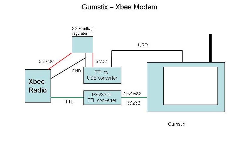
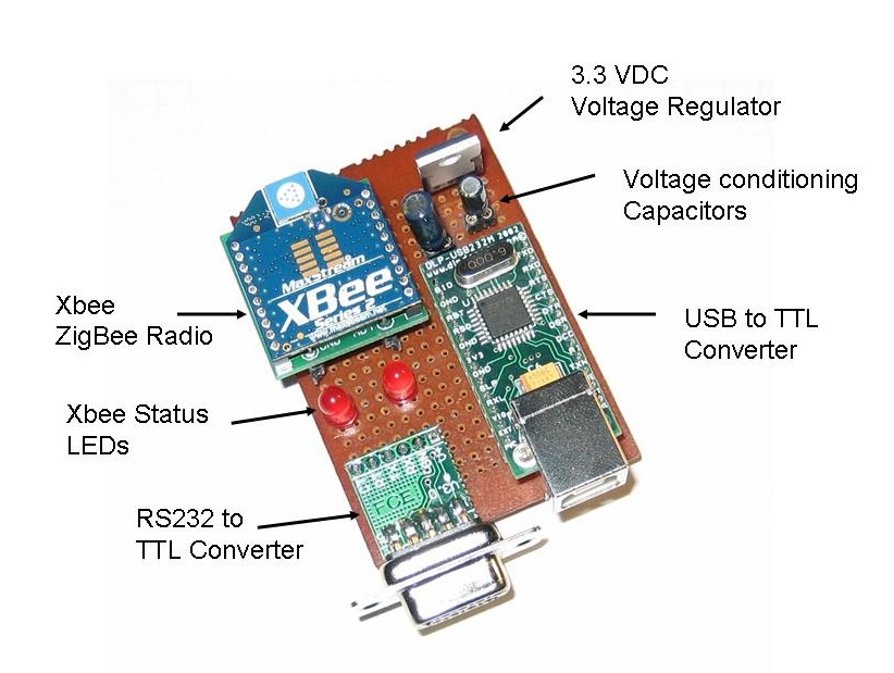
This shows the layout of the board. Very neat! This actually uses the Sparkfun Xbee breakout board (Sparkfun part number BOB-08276) which just provides a simple breakout for the Xbee pins rather than the complete power package on the Lady Ada carrier board I used on the Indoor-Outdoor Temperature Display. There is no design reason for this. I just happened to build this unit before I had discovered the Lady Ada breakout board. This is why I needed to put in a separate 3.3 VDC voltage regulator and the two power conditioning capacitors.
Now to continue with documenting the Remote Sensor rig, this section will describe the physical hardware that is used to interface the Gumstix server via Xbee to the Remote Sensor box and the Indoor-Outdoor Temperature display described earlier. I will discuss the PHP scripts running on the Gumstix in a later post.
The astute observer will note that this circuit is actually rather silly. Why is there an RS232-TTL converter and a USB-TTL converter? The answer is that the Gumstix does not at this point support the FTDI USB-Serial chip, but I needed something to power the circuit so I could avoid having an extra wall-wart in the picture. So, a very good DLP USB converter (Digi-key part 813-1018-ND) is essentially being totally wasted. I did try just pulling the power directly off a USB connector, but it didn't seem to be sufficient to run the Xbee, so the DLP Converter is obviously doing some sort of power conditioning along the way.
This shows the layout of the board. Very neat! This actually uses the Sparkfun Xbee breakout board (Sparkfun part number BOB-08276) which just provides a simple breakout for the Xbee pins rather than the complete power package on the Lady Ada carrier board I used on the Indoor-Outdoor Temperature Display. There is no design reason for this. I just happened to build this unit before I had discovered the Lady Ada breakout board. This is why I needed to put in a separate 3.3 VDC voltage regulator and the two power conditioning capacitors.
There is a 10 uF capacitor on the 5 VDC input of the regulator and a 1 uF on the 3.3 VDC output. I ain't no expert on this stuff, but what I understand is if they ain't there it ain't workin'.
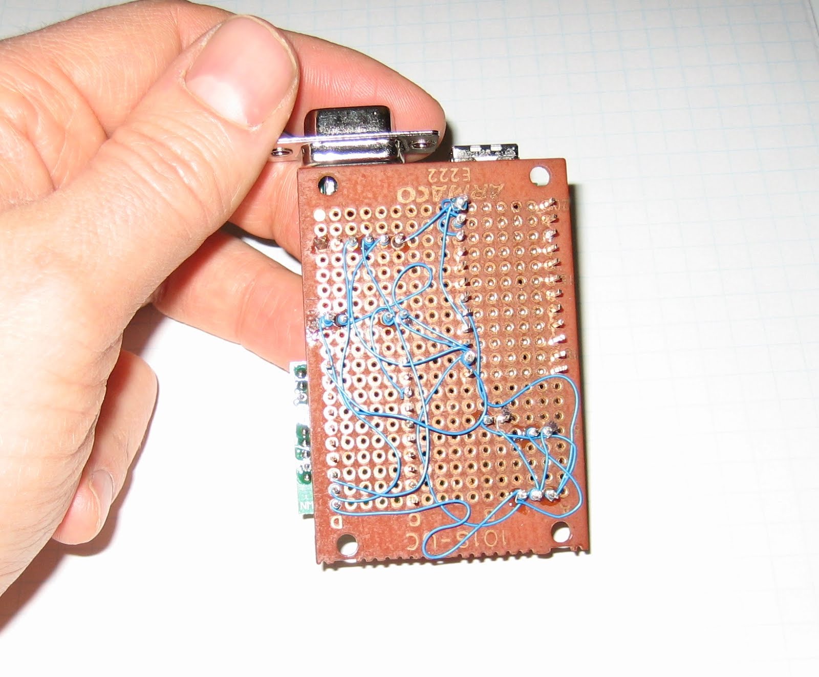
Again, this circuit is built using wire wrap, which provides a quick way to make a reasonably permanent circuit. I should be good and color code the power, ground and data wires and arrange them all more neatly, but I'm sure that will come with practise.
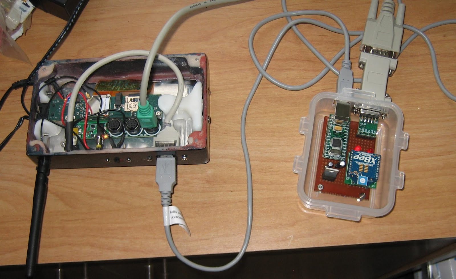
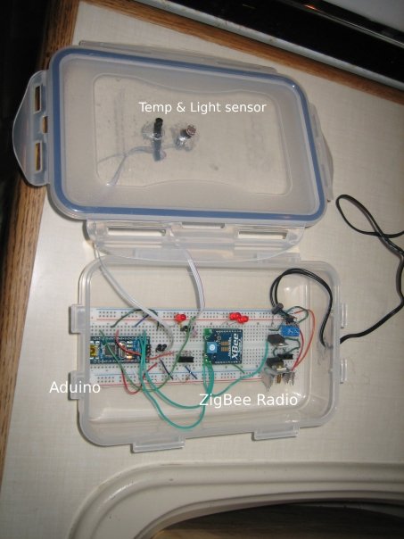
And here is the completed unit in the inevitable plastic food container. The Gumstix case is my own design (described here). The RS232 comes off of the Gumstix LCD-Serial board and through a gender changer to the RS232-TTL converter. The USB connects to the USB on the converter. The Arduino units communicated with the Xbee on this and the Gumstix then communicates over Wi-Fi to my home network.
Next post, I will describe the software that runs everything!
Again, this circuit is built using wire wrap, which provides a quick way to make a reasonably permanent circuit. I should be good and color code the power, ground and data wires and arrange them all more neatly, but I'm sure that will come with practise.
And here is the completed unit in the inevitable plastic food container. The Gumstix case is my own design (described here). The RS232 comes off of the Gumstix LCD-Serial board and through a gender changer to the RS232-TTL converter. The USB connects to the USB on the converter. The Arduino units communicated with the Xbee on this and the Gumstix then communicates over Wi-Fi to my home network.
Next post, I will describe the software that runs everything!
Saturday, January 17, 2009
Indoor Outdoor Temp Display
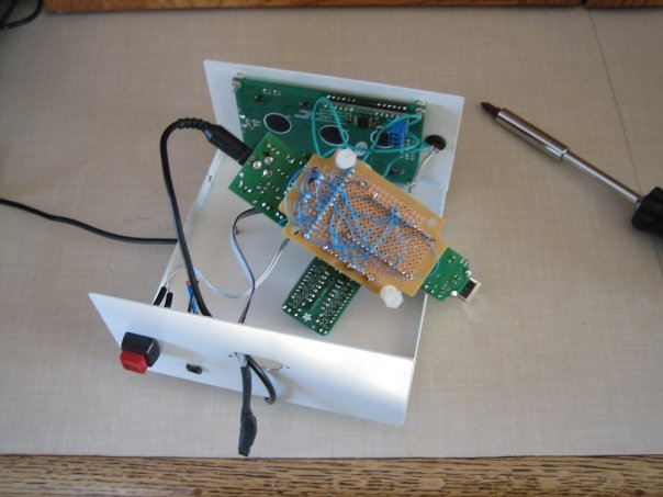
OK, it's time to move on with the remote sensor network description. Now for the Indoor-Outdoor Temp display, which is right now sitting faithfully beside my desk:

This uses a local DS18B20 Onewire temp sensor and the following standard components:
The first four items all came as kits which were assembled in less than 20 minutes. The big advantage of this approach is I am then just gluing together stuff others have built rather than having to build everything from scratch. The Adafruit XBee adapter, for instance, automatically adjusts the voltage down to 3.3 VDC (with the conditioning capacitors) and brings all the connections out neatly rather than having to hunt on the Xbee's pins. Slick.
Here is another hard to interpret schematic (click for full size):
 And here it all is installed in a project box I bought from Jameco a while back:
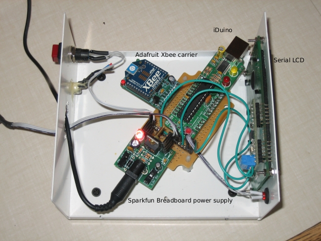
The circuit is built using wire wrap, which is a lightly "olde timey" way to do a circuit board. I rather like it because it is more permanent than a breadboard, but not nearly as much hassle as making a printed circuit board.
This uses a local DS18B20 Onewire temp sensor and the following standard components:
- Sparkfun SerialLCD (Sparkfun SKU LCD-00462)
- Sparkfun Breadboard Power Supply (Sparkfun SKU PRT-08376)
- Fundamental Logic iDuino
- Adafruit Xbe Adapter board
- Digi Xbee Radio (Digikey part number XB24-BCIT-004-ND)
The first four items all came as kits which were assembled in less than 20 minutes. The big advantage of this approach is I am then just gluing together stuff others have built rather than having to build everything from scratch. The Adafruit XBee adapter, for instance, automatically adjusts the voltage down to 3.3 VDC (with the conditioning capacitors) and brings all the connections out neatly rather than having to hunt on the Xbee's pins. Slick.
Here is another hard to interpret schematic (click for full size):

Now, what is that switch for? It actually doesn't control the power, but rather is hooked to digital pin 6 on the iDuino. When the switch is tripped, it sends out the "h" command over the Xbee which turns on LED2 on my remote unit. All this really demonstrates is the ability to send simple I/O back to the remote sensor from the indoor display. Not very practical, but remember that this is all just a prototype for something that does real work remotely!
The source code is shown below. The interesting thing is that this uses both the hard serial port on the Arduino and the Lady Ada AFSerial library (click here for more info ) to create a second soft serial port off of pins 2 & 3 on the iDuino. The interesting thing about this is that I found I could NOT use the Arduino software serial library (found here). While I have been able to use this oibrary to send info to the SerialLCD display, it will not receive serial properly - if there is a call to the hardware serial port, then the Arduino software serial port no longer works. The funny thing is the AFSerial library from Laday Ada works perfectly - just like another hardware serial port. No idea why.
Again, a lot of this code is concerned with running the DS18B20 Onewire temperature sensor.
/* Indoor display for Indoor Outdoor thermometer copyright Chris Armour */ #include#define TEMP_PIN 5 AFSoftSerial mySerial = AFSoftSerial(3,2); void OneWireReset(int Pin); void OneWireOutByte(int Pin, byte d); byte OneWireInByte(int Pin); int i = 0; int incomingNumber[4]; int incomingByte = 0; char outMinusBit = '+'; int outTempDig1 = 0; int outTempDig2 = 0; int ButtonPin = 6; int LEDPin = 12; int switchState = 0; long previousMillis = 0; long interval = 3000; void setup() { Serial.begin(9600); digitalWrite(TEMP_PIN, LOW); pinMode(TEMP_PIN, INPUT); // sets the digital pin as input (logic 1) mySerial.begin(9600); pinMode(ButtonPin, INPUT); pinMode(LEDPin, OUTPUT); } void loop() { // ======= The following is all code to control the OneWire sensor ==========// int HighByte, LowByte, TReading, SignBit, Tc_100, Whole, MinusBit; OneWireReset(TEMP_PIN); OneWireOutByte(TEMP_PIN, 0xcc); OneWireOutByte(TEMP_PIN, 0x44); // perform temperature conversion, strong pullup for one sec OneWireReset(TEMP_PIN); OneWireOutByte(TEMP_PIN, 0xcc); OneWireOutByte(TEMP_PIN, 0xbe); LowByte = OneWireInByte(TEMP_PIN); HighByte = OneWireInByte(TEMP_PIN); TReading = (HighByte << 8) + LowByte; SignBit = TReading & 0x8000; // test most sig bit if (SignBit) // negative { TReading = (TReading ^ 0xffff) + 1; // 2's comp } Tc_100 = (6 * TReading) + TReading / 4; // multiply by (100 * 0.0625) or 6.25 Whole = Tc_100 / 100; // separate off the whole and fractional portions //=========> End of the OneWire code MinusBit is the +/- & Whole is the temp ====/ //if (millis() - previousMillis > interval){ // previousMillis = millis(); if (Serial.available() > 0) { //Read the first four characters when serial is received from the Xbee for (int i=0; i <= 4; i ++){ // read the incoming byte: incomingByte = Serial.read(); incomingNumber[i] = incomingByte - 48; } Serial.flush(); //Discard the rest } if (incomingNumber[0] == 1) // Test if the first bit in indicates a positive or negative temp. { outMinusBit = '-'; } else if (incomingNumber[0] == 0) { outMinusBit = '+'; } outTempDig1 = incomingNumber[2]; //Assign the first digit of the temp outTempDig2 = incomingNumber[3]; //Assign the 2nd digit of the temp //Clear the LCD screen delay(1); Serial.print(254, BYTE); delay(1); Serial.print(1, BYTE); delay(1); //Print out the inside temp Serial.print("Inside Temp: "); if (SignBit) // If its negative { MinusBit = 1; Serial.print("-"); } else { MinusBit = 0; Serial.print("+"); } delay(1); Serial.print(Whole); //Print out the outside temp Serial.print(" "); Serial.print("Outside Temp: "); Serial.print(outMinusBit); Serial.print(outTempDig1); //Only print the 2nd digit if there is a positive value if (outTempDig2 >= 0){ Serial.print(outTempDig2); } else { Serial.print(" "); } //take a break delay(2000); mySerial.print(103, BYTE); //} switchState = digitalRead(ButtonPin); delay(100); if (switchState == 1){ digitalWrite(LEDPin, HIGH); mySerial.print(104, BYTE); } else { digitalWrite(LEDPin, LOW); mySerial.print(108, BYTE); } } //=============OneWire functions below==============// void OneWireReset(int Pin) // reset. Should improve to act as a presence pulse { digitalWrite(Pin, LOW); pinMode(Pin, OUTPUT); // bring low for 500 us delayMicroseconds(500); pinMode(Pin, INPUT); delayMicroseconds(500); } void OneWireOutByte(int Pin, byte d) // output byte d (least sig bit first). { byte n; for(n=8; n!=0; n--) { if ((d & 0x01) == 1) // test least sig bit { digitalWrite(Pin, LOW); pinMode(Pin, OUTPUT); delayMicroseconds(5); pinMode(Pin, INPUT); delayMicroseconds(60); } else { digitalWrite(Pin, LOW); pinMode(Pin, OUTPUT); delayMicroseconds(60); pinMode(Pin, INPUT); } d=d>>1; // now the next bit is in the least sig bit position. } } byte OneWireInByte(int Pin) // read byte, least sig byte first { byte d, n, b; for (n=0; n<8 br="" n=""> { digitalWrite(Pin, LOW); pinMode(Pin, OUTPUT); delayMicroseconds(5); pinMode(Pin, INPUT); delayMicroseconds(5); b = digitalRead(Pin); delayMicroseconds(50); d = (d >> 1) | (b<<7 and="" b="" bit="" br="" d="" in="" insert="" most="" position="" right="" shift="" sig="" to=""> } return(d); }
Monday, January 12, 2009
My Arduino Sensor Network
Alright, now has come the time to start discussing the meat of my development projects, which is a very simple sensor network linked via Zigbee radio. In itself, this isn't really terribly useful. All it does is record outside temperature and light levels and then display them with a serial-LCD display by my desk. You could do most of this with a simple wireless indoor-outdoor thermometer from Canadian Tire! However, what I am really building towards is building the control system for a solar pool heater for next summer's pool season so I don't have to faint from hypothermia every time I go for a swim.
Here is a diagram of the current system:

The three components are - each will be discussed in their own posts:
Here is a diagram of the current system:

- Gumstix webserver & data logger - This uses a Gumstix Linux box and a simple RS232 link to talk to an Xbee Zigbee radio from Digi (formerly Maxstream). Click here for more info on the radios.
- Indoor display & indoor temp sensor - This displays the indoor temp from a local sensor and the outdoor temp from the remote.
- Remote light & temp sensor - I will discuss this in more detail next.
Remote Sensor unit:
This is probably the most critical unit. It contains:

- A DS1820 OneWire precision temperature sensor
- A photoresistor light sensor
- The on-bard Arduino LED connected to digital pin 13 shows whether the light level has crossed a threshold
- The other LED is to test sending commands over the Xbee
- It can optionally have a moisture detector, but I have taken this out for now
- Power regulators for 5 VDC (for the Arduino) and 3.3 VDC for the Xbee

Here is a view showing the layout of the components when it was using my Arduino Nano:
And here is a more resent shot showing it with my new DuinoStamp installed:
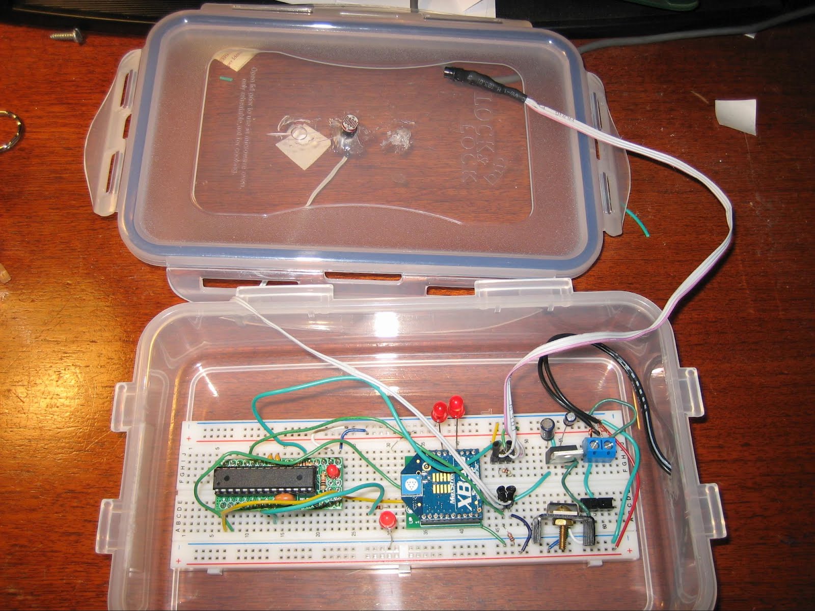
Good heavens I do sloppy breadboard installations! The plastic food container idea comes from Tom Igoe's excellent Making Things Talk, which is definitely the first book to buy if you are interested in this stuff. The box is reasonably weatherpoof and I have had this running outdoors for quite a while with no problems.
The firmware for the remote is reasonably simple, it checks the state of the two sensors (three if the moisture detector is installed) and the values received via the Xbee serial link. If a "g" character (ASCII 103) then the Arduino pushes out the values of the sensors and the state of the two on-board LEDs out over the Xbee. If an "h" is received (ASCII 104) then the Arduino turns on LED 2 connected to digital pin 7. If an "l" is received (ASCII 108) then the LED is turned off.
For those who absolutely have to see the source code, it is posted here. There is a lot of material related to the OneWire digital temp sensor that, frankly, I don't understand, but I borrowed from here.
That should be enough for now. Next up will be the Gumstix webserver & data logger.
Sunday, January 11, 2009
Another darned *Duino!
UPDATE: This Arduino clone no longer seems to be available and the links below are now dead. I leave this up here for historical background. Also, the hookup to a USB adapter is still valid for other "Duinos without a USB port.
Just a short post to document my most recent acquisition, which is yet another form factor/variant of the Arduino, this time the DuinoStamp. This is a small, breadboardable version of the Arduino which is described at Spifie.org and orderable from Fundamental Logic (click here to go to their order page). It cost less than $10 for the kit, so I went crazy and ordered four just to have a stock of spare ones.
This comes as a very straightforward kit that takes all of about 15 minutes to solder up. Here is what it looks like all done up on a breadboard:
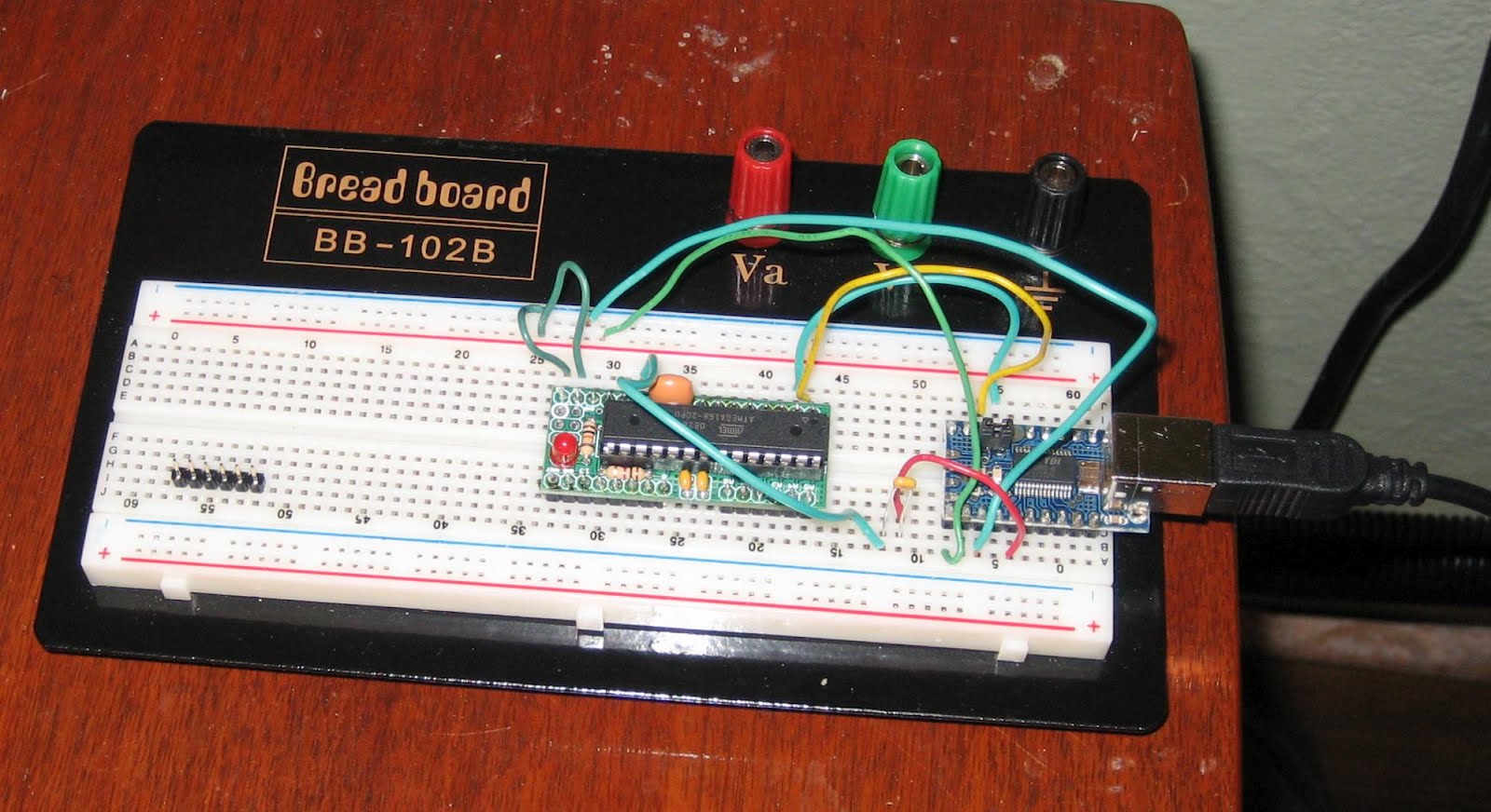
This is a very basic *Duino that doesn't include a built in USB interface (similar to the Arduino Mini, but a bit bigger). You therefore need to rig it up to an external USB to TTL serial converter, which is where I ran into a minor hiccup.
The problem is that on the new model Arduinos, they load up software very nicely and you don't need to do anything special, but with the older Arduino models you need to fiddle with the reset button at the exact right time to get them to upload new firmware. This is initially how I thought you had to use the DuinoStamp, but it was very frustrating trying to figure out the exact right timing for the reset and an error message that looks like:
avrdude: stk500_getsync(): not in sync: resp=0x60 avrdude: stk500_disable(): protocol error, expect=0x14, resp=0x66
(Whoever "Avrdude" is?). Anyway, I dropped a note to the Fundamental Logic people and Kevin got back to me right away and said the trick is to put a 0.1 uF capacitor between the RST pin on the DuinoStamp and the DTR pin on the USB adapter. Here is a rather crude scheamtic (click for full size):

So, now I can upload new firmware to the StampDuino, I shall try to port over some of my other projects to this new form factor.
Next up, I need to start describing my Xbee sensor network!
Just a short post to document my most recent acquisition, which is yet another form factor/variant of the Arduino, this time the DuinoStamp. This is a small, breadboardable version of the Arduino which is described at Spifie.org and orderable from Fundamental Logic (click here to go to their order page). It cost less than $10 for the kit, so I went crazy and ordered four just to have a stock of spare ones.
This comes as a very straightforward kit that takes all of about 15 minutes to solder up. Here is what it looks like all done up on a breadboard:
This is a very basic *Duino that doesn't include a built in USB interface (similar to the Arduino Mini, but a bit bigger). You therefore need to rig it up to an external USB to TTL serial converter, which is where I ran into a minor hiccup.
The problem is that on the new model Arduinos, they load up software very nicely and you don't need to do anything special, but with the older Arduino models you need to fiddle with the reset button at the exact right time to get them to upload new firmware. This is initially how I thought you had to use the DuinoStamp, but it was very frustrating trying to figure out the exact right timing for the reset and an error message that looks like:
avrdude: stk500_getsync(): not in sync: resp=0x60 avrdude: stk500_disable(): protocol error, expect=0x14, resp=0x66
(Whoever "Avrdude" is?). Anyway, I dropped a note to the Fundamental Logic people and Kevin got back to me right away and said the trick is to put a 0.1 uF capacitor between the RST pin on the DuinoStamp and the DTR pin on the USB adapter. Here is a rather crude scheamtic (click for full size):

So, now I can upload new firmware to the StampDuino, I shall try to port over some of my other projects to this new form factor.
Next up, I need to start describing my Xbee sensor network!
Saturday, January 3, 2009
More on the RFID updater
In the spirit of full disclosure, I thought I would describe a bit more of the internals of how the RFID Updater works for those who might be interested.
Here is what it actually looks like in Facebook:

This is generated by three different PHP files.
rfid_test.php - This one actually does the interaction with the serial port on my Gumstix to read the value of the most recent RFID card:
This writes the RFID tag number to a small file in the application directory. Note that this references the highly useful "php_serial.class.php" class which can be found at this location. I would be lost without the ability to interact with the serial port!
facebook_rfid.php - This presents the screen shown up above in Facebook and some basic info about me as a user and my last status. Most importantly, it calls up the "iFrame"!
The interesting thing to note here is line "$facebook->require_frame();". This was actually MISSING from the sample application provided by Facebook and without it nothing worked! It took a while to figure this out.
run_script.php - Finally, the actual script that changes the darned status! This is what runs inside the "iFrame". Why did I do it this way? Because, the main application PHP script cannot run an auto-refresh. With no refresh, it never bothers to detect the new RFID card!! So, the solution is to have a window running an iFrame (which is basically a window running another web page) that then has an auto-refresh which checks the RFID tag file periodically to see if it has changed. If it changes, then it spits out a new Facebook update.
Here is the script:
Here is what it actually looks like in Facebook:

This is generated by three different PHP files.
rfid_test.php - This one actually does the interaction with the serial port on my Gumstix to read the value of the most recent RFID card:
<?php
include "php_serial.class.php";
$tagfile = 'tag.txt';

// configure the serial port using php_serial.class.php
 $serial = new phpSerial;
 $serial->deviceSet("/dev/ttyS2");
 $serial->confBaudRate(9600);
 $serial->confParity("none");
 $serial->confCharacterLength(8);
 $serial->confStopBits(1);
 $serial->confFlowControl("none");
 $serial->deviceOpen();

 while(1){
  $rfidTag = $serial->readPort();
  if ($rfidTag != NULL) {
                 $filehandle = fopen($tagfile, "w");
   $rfidTagTrim = trim($rfidTag, "\x02..\x03");
   $rfidTagShort = substr($rfidTagTrim,7,5);
   print("The shortened tag is $rfidTagShort\n");
   fwrite($filehandle,$rfidTagShort);
   fclose($filehandle);
   if (strlen($rfidTagTrim) < 10) {
    echo "oops";
   }
  }
  usleep(1500000);
//  $serial->flush;
 }
?>
This writes the RFID tag number to a small file in the application directory. Note that this references the highly useful "php_serial.class.php" class which can be found at this location. I would be lost without the ability to interact with the serial port!
facebook_rfid.php - This presents the screen shown up above in Facebook and some basic info about me as a user and my last status. Most importantly, it calls up the "iFrame"!
<?php
// Copyright 2008 Chris Armour.  All Rights Reserved.
//
// Application: RFID Updater
//
// RFID updater updates your status based on various RFID tokens set
//up in the system.
//

require_once 'facebook.php';

$appapikey = 'XXXXXXXXXXXXXXXXXXX';
$appsecret = 'XXXXXXXXXXXXXXXXXXX';
$facebook = new Facebook($appapikey, $appsecret);
$facebook->require_frame();
$user_id = $facebook->require_login();

echo "<img style='width: 49px; height: 50px; float: left;' alt='' src='http://gumstix.dlinkddns.com/rfid_update/rfid_components_large.gif'>";
echo "<h1>  Radio Frequency ID Tag Status Updater</h1>";
echo "<br>";
echo "<br>";
echo "<br>";
echo "<fb:profile-pic uid='$user_id' linked='true' />";
echo "<p>Hello, <fb:name uid='$user_id' useyou='false'/>!</p>";
echo "<p>$user_id</p>";
echo "<p>Current status is: <fb:user-status uid='$user_id' linked='true'/></p>";
echo "<fb:prompt-permission perms='status_update'>Would you like to receive status updates from our application?</fb:prompt-permission>";
echo "<fb:prompt-permission perms='offline_access'>Do you want this application to have offline acceess?</fb:prompt-permission>";
echo "<fb:iframe src='http://gumstix.dlinkddns.com/rfid_update/run_script.php' style= 'width: 99%;height:350px' smartsize='false' frameborder='yes'>";
echo "</fb:iframe>";
?>
The interesting thing to note here is line "$facebook->require_frame();". This was actually MISSING from the sample application provided by Facebook and without it nothing worked! It took a while to figure this out.
run_script.php - Finally, the actual script that changes the darned status! This is what runs inside the "iFrame". Why did I do it this way? Because, the main application PHP script cannot run an auto-refresh. With no refresh, it never bothers to detect the new RFID card!! So, the solution is to have a window running an iFrame (which is basically a window running another web page) that then has an auto-refresh which checks the RFID tag file periodically to see if it has changed. If it changes, then it spits out a new Facebook update.
Here is the script:
<?php
// Copyright 2008 Chris Armour.  All Rights Reserved.
//
// Application: This is the script that actually detects the stat change and updates the status.
//
// RFID updater updates your status based on various RFID tokens set
//up in the system.
//

$logfile = 'log.txt';
$tagfile = 'tag.txt';
$filehandle1 = fopen($logfile, "r");
$filehandle2 = fopen($tagfile, "r");
$old_state = fread($filehandle1, filesize($logfile));
$tag_num = fread($filehandle2, filesize($tagfile));
fclose($filehandle1);
fclose($filehandle2);
require_once 'facebook.php';
$appapikey = 'XXXXXXXXXXXXXXXXXXXX';
$appsecret = 'XXXXXXXXXXXXXXXXX';
$facebook = new Facebook($appapikey, $appsecret);


echo "<!DOCTYPE html PUBLIC '-//W3C//DTD HTML 4.01 Transitional//EN'>";
echo "<html>";
echo "<head>";
echo "<meta content='text/html; charset=ISO-8859-1' http-equiv='content-type'>";
echo "<meta http-equiv='refresh' content='10'>";
echo "</head>";
echo "<body>";
$csv = "588777472";


if ($tag_num == $old_state){
 echo "<p>Place an RFID tag near the reader to update your status.<p>";
 }
 elseif ($tag_num != $old_state){
  switch($tag_num){
  case "51EAE":
   $result = $facebook->api_client->Users_setStatus('is gone for a workout.',false);
   echo "<p>Status changed to 51EAE - gone for a workout.</p>";
   echo "<p>Return code is = $result</p>";
$result=$facebook->api_client->notifications_sendEmail($csv,"RFID Status now gone for a workout", "RFID Updater has changed your status to Gone for a workout","<b><i><u>RFID Updater has reset status to gone for a workout.</u></i></b>");
   break;
  case "A503F":
   $result = $facebook->api_client->Users_setStatus('is not in the office',false);
   echo "<p>Status changed to A503F - not in the office</p>";
   echo "<p>Return code is = $result</p>";
$result=$facebook->api_client->notifications_sendEmail($csv,"RFID Status now not in the office", "RFID Updater has reset your status to not in the office","<b><i><u>RFID Updater has reset your status to not in the office.</u></i></b>");
   break;
         case "12B8F":
               $result = $facebook->api_client->Users_setStatus('is at work.',false);
                 echo "<p>Status changed to 12B8F - at work</p>";
                 echo "<p>Return code is = $result</p>";
$result=$facebook->api_client->notifications_sendEmail($csv,"RFID Status is at work", "RFID Updater has reset your status to at work","<b><i><u>RFID Updater has reset your status to at work.</u></i></b>");
   break;
         case "48EEF":
                 $result = $facebook->api_client->Users_setStatus('is testing the RFID updater',false);
                 echo "<p>Status changed to 48EEF - testing</p>";
                 echo "<p>Return code is = $result</p>";
$result=$facebook->api_client->notifications_sendEmail($csv,"RFID Status now Testing", "RFID Updater has reset your status to testing","<b><i><u>RFID Updater has reset your status to testing.</u></i></b>");
   break;
         case "5BC0C":
                 $result = $facebook->api_client->Users_setStatus('is watching TV',false);
                 echo "<p>status changed to 5BC0C - watching TV</p>";
                 echo "<p>Return code is = $result</p>";
$result=$facebook->api_client->notifications_sendEmail($csv,"RFID Status now watching TV", "RFID Updater has reset your status to watching TV","<b><i><u>RFID Updater has reset your status to watching TV.</u></i></b>");
   break;
  default:
   echo "<p>Card not read. Try again.</p>";
   }
  }
echo "</body>";
echo "</html>";

$old_state = $tag_num;
$filehandle3 = fopen($logfile, "w");
fwrite($filehandle3,$old_state);
fclose($filehandle3);

?>
Subscribe to:
Posts (Atom)


