Monday, March 16, 2009

Simple Arduino Fluid Control

Now that I am an actual iPhone user, I should be writing up a comparison with my i9 phone, but for now, another small Arduino project will have to suffice.

Diligent readers will remember that all this started with a desire on my part of make a solar pool heater using the the Arduino. Of course, the critical part of that is to be able to control valves & pumps and move liquid around.

This is my first project to start investigating this. This includes a 12 VDC solenoid valve that I bought off of eBay (click here for details) and a simple moisture detector circuit I previously used on another project. When the system starts up, the valve is closed and pushing the button off of Pin 12 opens the solenoid valve controlled by Pin 4. When the water level reaches the moisture detector on Pin 5, then the valve closes. To restart, you can lower lower the water level and push the button again and the cycle will run over.

Here is a video of the operation (keen observers will note that this is actually a more breadboardable iDuino not a proper "Arduino"):


Yes, the green colored water is in honor of Saint Patrick's Day and to make it easier to see.

Here is the circuit diagram:


I am gradually getting better with Eagle CAD!

The software is equally simple:

/*
Solenoid control
copyright Chris Armour 2009
 */

int ValvePin = 4;                // Solenoid valve connected to pin 4
int SwPin = 12;
int buttonWas = 0; // The state of the switch (pushed = 1, not pushed = 0) last time we looked
int buttonIs = 0; // Current state of the switch
int LEDPin = 13;
int MoistPin = 5;
int val = 0;

void setup()                    // run once, when the sketch starts
{
  pinMode(ValvePin, OUTPUT);      // sets the digital pin as output
  pinMode(SwPin, INPUT);
  pinMode(LEDPin, OUTPUT);
  Serial.begin(9600);
  buttonIs = digitalRead(SwPin); //Read the initial state of the switch!
}

//===========Functions=====================//
void getButton() { 
  buttonWas = buttonIs; // Set the old state of the button to be the current state since we're creating a new current state.
  buttonIs = digitalRead(SwPin); // Read the button state
} 

void openValve(){
    digitalWrite(ValvePin, HIGH);
    digitalWrite(LEDPin,HIGH);
    Serial.println("Valve Open");
}

void closeValve(){
  digitalWrite(ValvePin, LOW);
  digitalWrite(LEDPin,LOW);
  Serial.println("Valve closed");
}
  
//=================Main Loop===================//
void loop()                     // run over and over again
{
 getButton();
  
  if((buttonIs==1)&&(buttonWas==0)) { 
    openValve();
      }
  
  val = analogRead(MoistPin);
  
  if((val > 500)){ 
    closeValve();
      }
}


Putting the Valve Open & Valve Closed commands into functions greatly simplifies the main loop, which will make it easier to extend. The only tricky part was getting the momentary pushbutton switch initialized correctly. FOr some reason, it was always starting with the valve in the open state as if the button had been pushed. This requires you put the "buttonIs = digitalRead(SwPin);" into the setup section in order to get the right values set for the intial state of the switch. This seems a bit odd to me since I would have thought that this would be taken care of by the intial declaration of the variable. It must be something about the Arduiono boot up process that accidentally sets "buttonIs" to something unexpected!

Apologies for not posting this before, but here is a link to the original moisture detector circuit with a detailed explanation -> http://www.botanicalls.com/archived_kits/twitter/. A bit dated (like this article), but lots of good details.

That it for now. The next step will be to add in a pump so that when the water level is reached and the valve shuts the pump turns on and send the water back to the reservoir. This would make this a perpetual cycle of draining and pumping.

Sunday, February 15, 2009

RFID Arduino Door Lock

Back again after a short hiatus...

This project actually looks rather silly and this time I have a video to prove it! A while back I bought an Adafruit Motor Shield (click here for more info) and a couple of servo motors. I was looking around for a quick project when I remembered my old friend the RFID reader (which you will remember from this post). Perhaps because my day job involves the hotel industry, I thought why not have a try at building a door lock?

I am actually rather proud of this one, because I actually set about the design process in a proper organized fashion. I thought about what I wanted it to do and then drew a diagram of what pins I would use then I set about designing the software in a reasonably organized way. I must be getting the hang of this - only a moderate amount of banging my head on my desk!

Without further ado, here is the exciting multimedia part of tonight's presentation!


Now for a couple of quick pictures. This shows the inside mechanism:


And here is the RFID reader on the outside of the door:


Oh no, another poorly drawn Eagle CAD schematic:


Hardwarewise, it is very simple. The only oddity here is that I have actually used the Analog pins of the Arduino as Digital pins. This is done quite simply by calling them pins 14 - 19. Why? This is because the Motor Sheild either uses or covers up most of the usual digital pins. Really, for a simple servo motoro like this, I am not actually using all those digitial pins, and, in fact, I probably don't need the Motor Sheild at all. An Arduino can drive a simple servo without any extra circuitry. However, I wanted to set this up so that a stepper motor could be substituted in later on.

Software

So, here is the code that makes it work:
/* ======== Arduino RFID door lock ============

copyright Chris Armour, Feb 2009

*/

#include <AFSoftSerial.h> //Adafruit soft serial library - slightly modified!
#include <ServoTimer1.h> //Ada Motorshield servo library

// =========Initialize variables and so on =========================//
ServoTimer1 servo1;
AFSoftSerial rfidSerial =  AFSoftSerial(14,15);
//Note that this uses a version of the AFSoftSerial library modified to support pin numbers > 9.
int LEDPin = 16;
int incomingByte[16];
int oldCardNum = 0;
int newCardNum = 0;
int goodCardNum1 = 56;
int goodCardNum2 = 51;
int Angle = 0;
int LockState = 1; //1 = unlocked 0 = locked
int LockLED = 17;
int InButton = 18;
int buttonWas = 0; // The state of the switch (pushed = 1, not pushed = 0) last time we looked
int buttonIs = 0; // Current state of the switch

//==========Setup pins & servo ===============//
void setup() {
Serial.begin(9600);
rfidSerial.begin(9600);
pinMode(LEDPin, OUTPUT);
pinMode(LockLED, OUTPUT);
pinMode(InButton, INPUT);
servo1.attach(10);
servo1.write(Angle);
}

//===========Functions=====================//
void getButton() {
buttonWas = buttonIs; // Set the old state of the button to be the current state since we're creating a new current state.
buttonIs = digitalRead(InButton); // Read the button state
}

void openClose(){ //Evaluates the LockState variable
 digitalWrite(LEDPin, HIGH); //Turns on pass/fail LED
   if (LockState == 1){
     Angle = 180; //Turns servo to UNLOCKED position
     LockState = 0; //toggles Lockstate
     digitalWrite(LockLED,HIGH); //Turns on LockLED to show door UNLOCKED
     }
   else {
     Angle = 0; //turns servo to LOCKED position
     LockState = 1; //toggles lock state
     digitalWrite(LockLED,LOW); //Turns off LockLED to show door LOCKED
     }
   servo1.write(Angle); //Move the servo appropriately
   delay(1000);
   digitalWrite(LEDPin,LOW); //after 1 second, turn off the pass/fail LED
}

//================= Main loop =========================//

void loop() {

getButton();
if((buttonIs==1)&&(buttonWas==0)) { //If the button has been pushed, call openClose to toggle the state of the servo & LEDs.
 openClose();
   }

if(incomingByte[11] > 0){
 oldCardNum = incomingByte[11]; //Sets the value of the last read RFID card to oldCardNum. Just using the 12 digit of the card ID.
}

if(rfidSerial.available() > 0) { //If the AFSoftSerial RX pin reads new incoming data.
 for (int i=0; i <= 16; i++){ //It reads the next 16 characters
     delay(10);
 incomingByte[i] = rfidSerial.read();
     newCardNum = incomingByte[11]; //Pick out ASCII character #12 since it is unique across the 5 cards I have.
      }
  }

if(oldCardNum != newCardNum) {  //Check if a new card # has been received.
  if(newCardNum == goodCardNum1 || newCardNum == goodCardNum2){ //If the new card number equals either of the key cards.
    openClose(); //run the openClose function
   }
else { //If the card isn't a good card, flash the pass/fail indicator 3 times.
  for (int x=0; x <=3; x++){
  digitalWrite(LEDPin, HIGH);
   delay(100);
   digitalWrite(LEDPin,LOW);
   delay(100);
  }
}
Serial.println(newCardNum); //serial output for debugging.
}

}


I am actually rather proud of this code. It uses actual functions for getting the value of the button and for evaluating the lock/unlock state. Of the five RFID cards that I have, two of them are hard coded as "good cards" and the other three trigger the flashing LEDs as "bad cards".

The main thing to note in this software is that the Lady Ada AFSoftSerial library had to be modified to use the Analog Pins (i.e., digital pins in the range 14 to 19). Apparently the AFSoftSerial library is hard coded to work with pins below 13. This is the one time I actually had to ASK SOMEONE for help on something related to the Arduino (in contrast to the Gumstix, which took endless asking to get working!). Anyway, here is a link to the forum posting for those who are curious. It is a simple fix that user mtbf0 came up with, but it was over my head!!

That's enough for this project. This one was fun since it actually moves and potentially does useful work!

Wednesday, January 28, 2009

Gumstix Arduino Software

I would ask the programmers out there to bear with me! I am a pretty poor coder - probably the result of having two history degrees or being frequently dropped on my head as a child. I tend to not comment my code and I usually work from a single thing that works and just barnacle on elaborations rather than neatly putting things into functions and properly planning my work. I like working in PHP because it has all the ease of C without some of the traps (like handling strings or declaring variables).

So, for my sensor network, the Gumstix Linux box is running PHP 5.0 and the Cherokee web server. This seems to be very robust and I haven't had to reboot it in ages. The main webpage comes up on my internal network like this:


This displays the main info off of the remote sensors and also takes an RSS feed off of www.weatherunderground.com for the current weather in Hamilton, Ontario. This allows me to cross-check the temp readings with the actual weather reported for the area. Note that this still includes a "moisture" reading, but the sensor is now been taken off the system. This was my attempt to detect if it was raining or not based on this circuit from Rob Faludi.

The LED2 On button allows me to control the secondary LED on the remote unit. This is essentially just a way to test remote controlling a digital output over the web and the Zigbee link. When you click the button, it launches a small script that sends out an "h", which turns the light ON. The button will then toggle to the "off" mode and when you press it again it sends an "l" (lower case L) to turn off the LED.

Below is the source code in all it's messy glory. It uses the indispensable "php_serial.class.php" class from Remy Sanchez (found here ) which is absolutely essential to do anything between PHP and your serial port. The script then grabs the Weather Underground RSS feed and generates the HTML to load the web page.

Arduino.php:

<?php
include "php_serial.class.php";

// configure the serial port using php_serial.class.php
 $serial = new phpSerial;
 $serial->deviceSet("/dev/ttyS2");
 $serial->confBaudRate(9600);
 $serial->confParity("none");
 $serial->confCharacterLength(8);
 $serial->confStopBits(1);
 $serial->confFlowControl("none");
 $serial->deviceOpen();

 $serial->sendMessage("g");
 usleep(100000);
 $serial->flush;
 $read = $serial->readPort();
 $ard_array = explode(',',$read,7);

 if (empty($ard_array[6])){
  usleep(100000);
  $serial->sendMessage("g");
  usleep(100000);
  $read = $serial->readPort();
  $ard_array = explode(',',$read,7); 
 }

 if ($ard_array[0] == 1) {
  $plusMinus = "-";
 } elseif ($ard_array[0] == 0){
  $plusMinus = "+";
 }

$weather = 
simplexml_load_file('http://www.weatherunderground.com/auto/rss_full/global/stations/71297.xml?units=both');

echo "<!DOCTYPE html PUBLIC '-//W3C//DTD HTML 4.01 Transitional//EN'>";
echo "<html>";
echo "<head>";
echo "<meta content='text/html; charset=ISO-8859-1'
 http-equiv='content-type'>";
echo "<meta http-equiv='refresh' content='6'>";
echo "<img style='float: left; width: 81px; height: 90px;' 
src='images/arduino-nano.jpg'>";
echo " <title>Arduino Control</title>";
echo "</head>";
echo "<body>";
echo "<br>";
echo "<h1><span style='font-family: Arial;'>Arduino Control Panel</h1>";
echo "<br></br>";
echo "<table style='text-align: left; width: 50%;' border='1'
 cellpadding='2' cellspacing='2'>";
echo "<tbody>";
echo "<tr>";
echo "<th>Deg C</th>";
echo "<th>Light Level</th>";
echo "<th>LED 1 ON/OFF</th>";
echo "<th>Moisture</th>";
echo "<th>LED 2 ON/OFF</th></tr>";
echo "<tr>";
echo "<td>$plusMinus$ard_array[1]</td>";
echo "<td>$ard_array[2]</td>";
echo "<td>$ard_array[3]</td>";
echo "<td>$ard_array[4]</td>";
echo "<td>$ard_array[5]</td>";
echo "</tr>";
echo "</tbody>";
echo "</table>";
echo "<br>";
echo "<h2><span style='font-family: Arial;'>Current Weather in Hamilton</h2>";
foreach ($weather->channel->item as $item) {
                $w = $item->description . "";
                $newchar = str_replace("|", "", $w);
                $newestchar = str_replace("Temperature","Current temp", $newchar);
                $newest2char = str_replace("°F","F",$newestchar);
                $newest3char = str_replace("°C","C",$newest2char);
                $newest4char = str_replace("percent","%",$newest3char);
                $newest5char = str_replace(" / "," ",$newest4char);
                $newest6char = str_replace("  "," ",$newest5char);
                $newest7char = str_replace("Direction:","Dir:",$newest6char);
                $newerchar = trim($newest7char);
                $wchar = substr($newerchar,0,80);

$wchar = substr($newerchar,0,300);

echo "<table style='text-align: left; width: 50%;' border='1'
 cellpadding='2' cellspacing='2'>";
echo "<tbody>";
echo "<tr>";
echo "<td>$wchar</td>";
echo "</tr>";
echo "</tbody>";
echo "</table>";
                }

echo "<br>";
echo "<a href='arduino_data2.php'>View Log</a><br>";
echo "<br>";
echo "<table>";
echo "<tbody>";
echo "<tr>";
echo "<td>";
if ($ard_array[5] == 1) {

echo "<form action='led_off.php' method='get'>"; 
echo "<input type='hidden' name='variablename' value='variablevalue'>"; 
echo "<input type='submit' value='TURN LED2 OFF'/>";
echo "</form>";
}
if ($ard_array[5] == 0){
echo "</td>";
echo "<td>";
echo "<form action='led_on.php' method='get'>";
echo "<input type='hidden' name='variablename' value='variablevalue'>";
echo "<input type='submit' value='TURN LED2 ON'/>";
echo "</form>";
}
echo "</td>";
echo "</tbody>";
echo "</table>";
echo "<br>";
echo "<hr style='width: 100%; height: 2px;'>";
echo "<br>";
echo "<img style='float: left; width: 81px; height: 90px;' 
src='images/gumlogo.gif'>";
echo "<h1><span style='font-family: Arial;'>Gumstix Controls</h1>";
echo "<br>";
echo "<table>";
echo "<tbody>";
echo "<td>";
echo "<form action='turn_off.php' method='get'>";
echo "<input type='hidden' name='variablename' value='variablevalue'>";
echo "<input type='submit' value='TURN OFF GUMSTIX'/>";
echo "</td><td>";
echo "</form>";
echo "<form action='reboot_gum.php' method='get'>";
echo "<input type='hidden' name='variablename' value='variablevalue'>";
echo "<input type='submit' value='REBOOT GUMSTIX'/>";
echo "</form>";
echo "</td>";
echo "</tbody>";
echo "</table>";
echo "<hr style='width: 100%; height: 2px;'>";
echo "<img src='images/powered_by_cherokee.png'>";
echo "</body>";
echo "</html>";

$serial->deviceClose();

?>


The other function of the Gumstix is also to act as a data logger. Clicking the link for the log takes you to this page:


This is a very small SQLite database that keeps track of the readings of the remote units sensors. The code below uses a PDO statement to open the database and generate the HTML to display its contents. Eventually, I will need to put some further refinements on it so you can select results from different days and maybe graph the temerature.

Arduino_data2.php:

<?php

$db = new PDO('sqlite:/media/card/back_up/home/root/arduino.db');
$st = $db->query('SELECT * FROM tbl');
$results = $st->fetchAll();
echo "<!DOCTYPE html PUBLIC '-//W3C//DTD HTML 4.01 Transitional//EN'>";
echo "<html>";
echo "<head>";
echo "<meta content='text/html; charset=ISO-8859-1'
 http-equiv='content-type'>";
echo "<meta http-equiv='refresh' content='10' >";
echo " <title>Data Log</title>";
echo "</head>";
echo "<body>";
echo "<h1>Arduino Data Log</h1>";
echo "<br></br>";
echo "<form action='clear_log.php')'>";
echo "<input type='submit' value='Clear Log'/>";
echo "</form>";
echo "<table style='text-align: left; width: 50%;' border='1'
 cellpadding='2' cellspacing='2'>";
echo "<tbody>";
echo "<tr>";
echo "<th>Index</th>";
echo "<th>Date-Time</th>";
echo "<th>Light Level</th>";
echo "<th>LED1</th>";
echo "<th>Moisture</th>";
echo "<th>LED2</th>";
echo "<th>+/-</th>";
echo "<th>Temp</th>";
echo "</tr>";

$rows = count($results);
 
 for ($i=0; $i <= $rows; $i++){
  echo "<tr>";
  for ($x=0; $x <= 7; $x++){
   echo "<td>{$results[$i][$x]}</td>";
  }
  echo "</tr>";
 }
echo "</tbody>";
echo "</table>";
echo "<br>";
echo "<a href='arduino.php'>Return to Control Panel</a><br>";
echo "</body>";
echo "<html>";
$db = null;

?>


How does the data actually get into the database? This is pretty straightforward. Read the serial port with the aforementioned PHP serial class and put the results into an array, then use the SQL INSERT command to put it into the database:

data_logging.php:

<?php
include "php_serial.class.php";

// configure the serial port using php_serial.class.php
   $serial = new phpSerial;
   $serial->deviceSet("/dev/ttyS2");
   $serial->confBaudRate(9600);
   $serial->confParity("none");
   $serial->confCharacterLength(8);
   $serial->confStopBits(1);
   $serial->confFlowControl("none");
   $serial->deviceOpen();

   $serial->sendMessage("g");
   usleep(100000);
   $serial->flush;
   $read = $serial->readPort();
   $ard_array = explode(',',$read,7);
   $serial->deviceClose();
   if ($ard_array[0] == 0){
       $ard_array[0] = "'+'";
       }
   elseif ($ard_array[0] == 1){
       $ard_array[0] = "'-'";
       }
//print_r($ard_array);

putenv("TZ=UTC+5");


$db = new PDO('sqlite:/media/card/back_up/home/root/arduino.db');
$db->exec("INSERT INTO tbl (lightLev,LED1,SW1,LED2,plus_minus,temp)
VALUES
($ard_array[2],$ard_array[3],$ard_array[4],$ard_array[5],$ard_array[0],$ard_array[1])");

Print("Insert successful\n");

?>


This is driven by a crontab item on the Gumstix that runs every 15 minutes. For those out there who might be struggling to figure out crontab on Linux, the way I did this was via the command "crontab -e" and I included the line:

*/15 * * * * /usr/bin/php /var/www/data_logging.php > /dev/null

Well, that should be enough for now on my sensor network project. Soon, I will have to start actually building some of the elements of the solar pool heater concept that started all this. I now have some solenoid valves and a small pump, so I need to do a proptype of an Arduino managing flud control. Maybe I might do something again with RFID first!

Gumstix-Xbee Modem Hardware

Hola Amigos!

Now to continue with documenting the Remote Sensor rig, this section will describe the physical hardware that is used to interface the Gumstix server via Xbee to the Remote Sensor box and the Indoor-Outdoor Temperature display described earlier. I will discuss the PHP scripts running on the Gumstix in a later post.

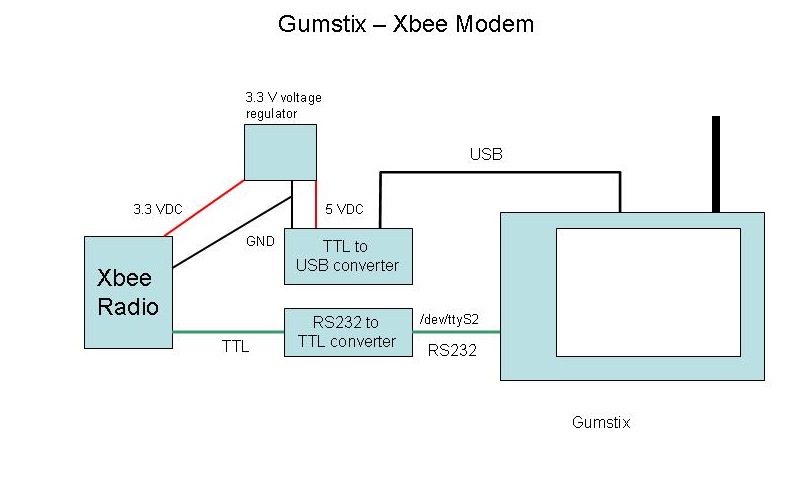
The astute observer will note that this circuit is actually rather silly. Why is there an RS232-TTL converter and a USB-TTL converter? The answer is that the Gumstix does not at this point support the FTDI USB-Serial chip, but I needed something to power the circuit so I could avoid having an extra wall-wart in the picture. So, a very good DLP USB converter (Digi-key part 813-1018-ND) is essentially being totally wasted. I did try just pulling the power directly off a USB connector, but it didn't seem to be sufficient to run the Xbee, so the DLP Converter is obviously doing some sort of power conditioning along the way.


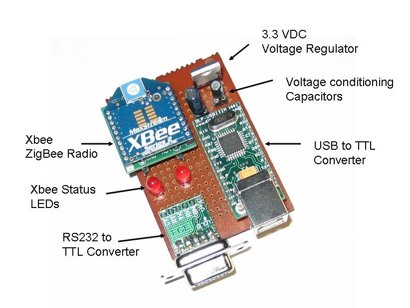
This shows the layout of the board. Very neat! This actually uses the Sparkfun Xbee breakout board (Sparkfun part number BOB-08276) which just provides a simple breakout for the Xbee pins rather than the complete power package on the Lady Ada carrier board I used on the Indoor-Outdoor Temperature Display. There is no design reason for this. I just happened to build this unit before I had discovered the Lady Ada breakout board. This is why I needed to put in a separate 3.3 VDC voltage regulator and the two power conditioning capacitors.

There is a 10 uF capacitor on the 5 VDC input of the regulator and a 1 uF on the 3.3 VDC output. I ain't no expert on this stuff, but what I understand is if they ain't there it ain't workin'.


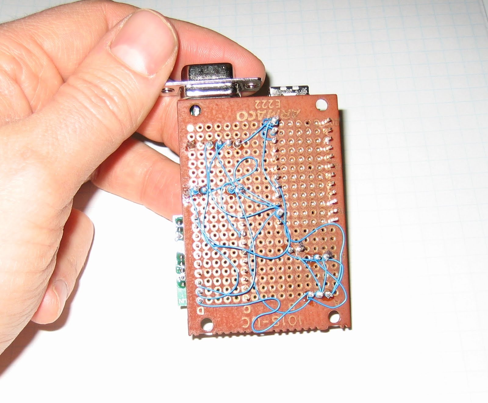
Again, this circuit is built using wire wrap, which provides a quick way to make a reasonably permanent circuit. I should be good and color code the power, ground and data wires and arrange them all more neatly, but I'm sure that will come with practise.

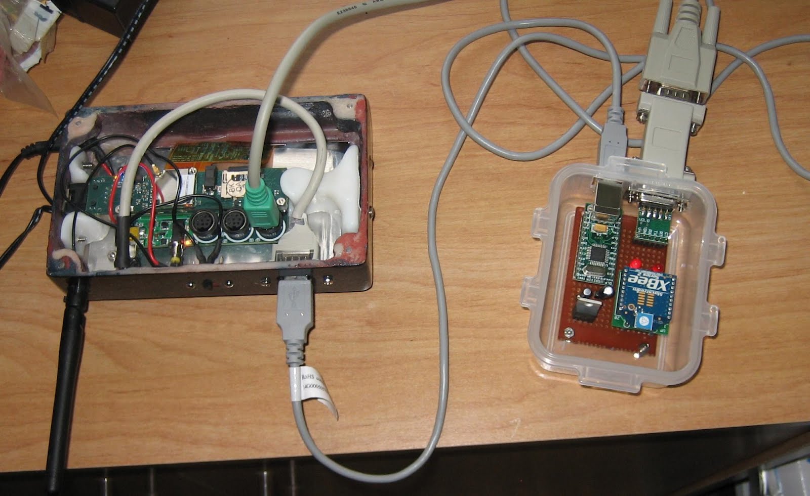
And here is the completed unit in the inevitable plastic food container. The Gumstix case is my own design (described here). The RS232 comes off of the Gumstix LCD-Serial board and through a gender changer to the RS232-TTL converter. The USB connects to the USB on the converter. The Arduino units communicated with the Xbee on this and the Gumstix then communicates over Wi-Fi to my home network.


Next post, I will describe the software that runs everything!

Saturday, January 17, 2009

Indoor Outdoor Temp Display

OK, it's time to move on with the remote sensor network description. Now for the Indoor-Outdoor Temp display, which is right now sitting faithfully beside my desk:


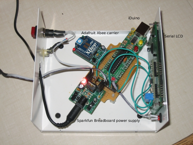
This uses a local DS18B20 Onewire temp sensor and the following standard components:


The first four items all came as kits which were assembled in less than 20 minutes. The big advantage of this approach is I am then just gluing together stuff others have built rather than having to build everything from scratch. The Adafruit XBee adapter, for instance, automatically adjusts the voltage down to 3.3 VDC (with the conditioning capacitors) and brings all the connections out neatly rather than having to hunt on the Xbee's pins. Slick.

Here is another hard to interpret schematic (click for full size):
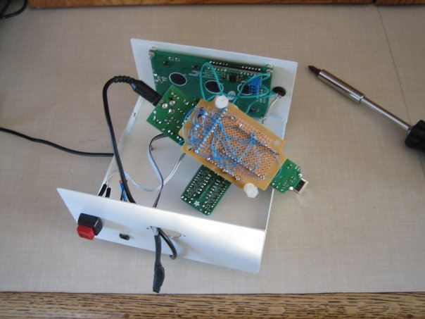
And here it all is installed in a project box I bought from Jameco a while back:


The circuit is built using wire wrap, which is a lightly "olde timey" way to do a circuit board. I rather like it because it is more permanent than a breadboard, but not nearly as much hassle as making a printed circuit board.


Now, what is that switch for? It actually doesn't control the power, but rather is hooked to digital pin 6 on the iDuino. When the switch is tripped, it sends out the "h" command over the Xbee which turns on LED2 on my remote unit. All this really demonstrates is the ability to send simple I/O back to the remote sensor from the indoor display. Not very practical, but remember that this is all just a prototype for something that does real work remotely!

The source code is shown below. The interesting thing is that this uses both the hard serial port on the Arduino and the Lady Ada AFSerial library (click here for more info ) to create a second soft serial port off of pins 2 & 3 on the iDuino. The interesting thing about this is that I found I could NOT use the Arduino software serial library (found here). While I have been able to use this oibrary to send info to the SerialLCD display, it will not receive serial properly - if there is a call to the hardware serial port, then the Arduino software serial port no longer works. The funny thing is the AFSerial library from Laday Ada works perfectly - just like another hardware serial port. No idea why.

Again, a lot of this code is concerned with running the DS18B20 Onewire temperature sensor.

/* Indoor display for Indoor Outdoor thermometer
copyright Chris Armour */

#include 

#define TEMP_PIN  5

AFSoftSerial mySerial =  AFSoftSerial(3,2);
void OneWireReset(int Pin);
void OneWireOutByte(int Pin, byte d);
byte OneWireInByte(int Pin);

int i = 0;
int incomingNumber[4];
int incomingByte = 0;
char outMinusBit = '+';
int outTempDig1 = 0;
int outTempDig2 = 0;
int ButtonPin = 6;
int LEDPin = 12;
int switchState = 0;
long previousMillis = 0;        
long interval = 3000;           

void setup() {
  Serial.begin(9600);
  digitalWrite(TEMP_PIN, LOW);
  pinMode(TEMP_PIN, INPUT);      // sets the digital pin as input (logic 1)
  mySerial.begin(9600);
  pinMode(ButtonPin, INPUT);
  pinMode(LEDPin, OUTPUT);
}

void loop() {

// ======= The following is all code to control the OneWire sensor ==========//
  int HighByte, LowByte, TReading, SignBit, Tc_100, Whole, MinusBit;
  OneWireReset(TEMP_PIN);
  OneWireOutByte(TEMP_PIN, 0xcc);
  OneWireOutByte(TEMP_PIN, 0x44); // perform temperature conversion, strong pullup for one sec

  OneWireReset(TEMP_PIN);
  OneWireOutByte(TEMP_PIN, 0xcc);
  OneWireOutByte(TEMP_PIN, 0xbe);

  LowByte = OneWireInByte(TEMP_PIN);
  HighByte = OneWireInByte(TEMP_PIN);
  TReading = (HighByte << 8) + LowByte;
  SignBit = TReading & 0x8000;  // test most sig bit
  if (SignBit) // negative
  {
    TReading = (TReading ^ 0xffff) + 1; // 2's comp
  }
  Tc_100 = (6 * TReading) + TReading / 4;    // multiply by (100 * 0.0625) or 6.25

  Whole = Tc_100 / 100;  // separate off the whole and fractional portions

//=========> End of the OneWire code MinusBit is the +/- & Whole is the temp ====/
//if (millis() - previousMillis > interval){
//  previousMillis = millis();
 if (Serial.available() > 0) {
//Read the first four characters when serial is received from the Xbee
   for (int i=0; i <= 4; i ++){
 // read the incoming byte:
 incomingByte = Serial.read();
        incomingNumber[i] = incomingByte - 48;
         }
         Serial.flush();
         //Discard the rest
     }
    
    if (incomingNumber[0] == 1) // Test if the first bit in indicates a positive or negative temp.
              {
                outMinusBit = '-';
              }
            else if (incomingNumber[0] == 0)
            {
              outMinusBit = '+';
            }
            outTempDig1 = incomingNumber[2]; //Assign the first digit of the temp
            outTempDig2 = incomingNumber[3]; //Assign the 2nd digit of the temp

  //Clear the LCD screen
  delay(1);
  Serial.print(254, BYTE);
  delay(1);
  Serial.print(1, BYTE); 
  delay(1);

//Print out the inside temp
  Serial.print("Inside Temp: ");
   if (SignBit) // If its negative
  {
    MinusBit = 1; 
    Serial.print("-");
  }
  else
  {
    MinusBit = 0;
    Serial.print("+");
  }
  
delay(1);
Serial.print(Whole);
//Print out the outside temp
Serial.print("    ");
Serial.print("Outside Temp: ");
Serial.print(outMinusBit);
Serial.print(outTempDig1);
//Only print the 2nd digit if there is a positive value
if (outTempDig2 >= 0){
    Serial.print(outTempDig2);
  }
  else {
    Serial.print(" ");
  }
//take a break
delay(2000);
  mySerial.print(103, BYTE);
//}

  switchState = digitalRead(ButtonPin);
delay(100);
if (switchState == 1){
  digitalWrite(LEDPin, HIGH);
  mySerial.print(104, BYTE);
}
else {
  digitalWrite(LEDPin, LOW);
  mySerial.print(108, BYTE);
}
} 

//=============OneWire functions below==============//

void OneWireReset(int Pin) // reset.  Should improve to act as a presence pulse
{
     digitalWrite(Pin, LOW);
     pinMode(Pin, OUTPUT); // bring low for 500 us
     delayMicroseconds(500);
     pinMode(Pin, INPUT);
     delayMicroseconds(500);
}

void OneWireOutByte(int Pin, byte d) // output byte d (least sig bit first).
{
   byte n;

   for(n=8; n!=0; n--)
   {
      if ((d & 0x01) == 1)  // test least sig bit
      {
         digitalWrite(Pin, LOW);
         pinMode(Pin, OUTPUT);
         delayMicroseconds(5);
         pinMode(Pin, INPUT);
         delayMicroseconds(60);
      }
      else
      {
         digitalWrite(Pin, LOW);
         pinMode(Pin, OUTPUT);
         delayMicroseconds(60);
         pinMode(Pin, INPUT);
      }

      d=d>>1; // now the next bit is in the least sig bit position.
   }
   
}

byte OneWireInByte(int Pin) // read byte, least sig byte first
{
    byte d, n, b;

    for (n=0; n<8 br="" n="">    {
        digitalWrite(Pin, LOW);
        pinMode(Pin, OUTPUT);
        delayMicroseconds(5);
        pinMode(Pin, INPUT);
        delayMicroseconds(5);
        b = digitalRead(Pin);
        delayMicroseconds(50);
        d = (d >> 1) | (b<<7 and="" b="" bit="" br="" d="" in="" insert="" most="" position="" right="" shift="" sig="" to="">    }
    return(d);
}

Monday, January 12, 2009

My Arduino Sensor Network

Alright, now has come the time to start discussing the meat of my development projects, which is a very simple sensor network linked via Zigbee radio. In itself, this isn't really terribly useful. All it does is record outside temperature and light levels and then display them with a serial-LCD display by my desk. You could do most of this with a simple wireless indoor-outdoor thermometer from Canadian Tire! However, what I am really building towards is building the control system for a solar pool heater for next summer's pool season so I don't have to faint from hypothermia every time I go for a swim.

Here is a diagram of the current system:

The three components are - each will be discussed in their own posts:

  • Gumstix webserver & data logger - This uses a Gumstix Linux box and a simple RS232 link to talk to an Xbee Zigbee radio from Digi (formerly Maxstream). Click here for more info on the radios.
  • Indoor display & indoor temp sensor - This displays the indoor temp from a local sensor and the outdoor temp from the remote.
  • Remote light & temp sensor - I will discuss this in more detail next.

Remote Sensor unit:

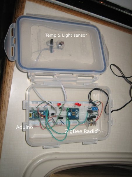
This is probably the most critical unit. It contains:
  • A DS1820 OneWire precision temperature sensor
  • A photoresistor light sensor
  • The on-bard Arduino LED connected to digital pin 13 shows whether the light level has crossed a threshold
  • The other LED is to test sending commands over the Xbee
  • It can optionally have a moisture detector, but I have taken this out for now
  • Power regulators for 5 VDC (for the Arduino) and 3.3 VDC for the Xbee
Here is a rather idiosyncratic schematic (click to see full size):


Here is a view showing the layout of the components when it was using my Arduino Nano:


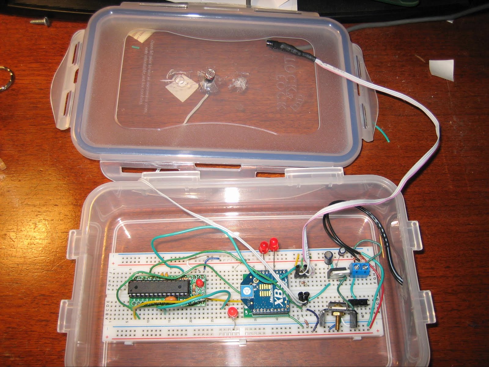
And here is a more resent shot showing it with my new DuinoStamp installed:


Good heavens I do sloppy breadboard installations! The plastic food container idea comes from Tom Igoe's excellent Making Things Talk, which is definitely the first book to buy if you are interested in this stuff. The box is reasonably weatherpoof and I have had this running outdoors for quite a while with no problems.

The firmware for the remote is reasonably simple, it checks the state of the two sensors (three if the moisture detector is installed) and the values received via the Xbee serial link. If a "g" character (ASCII 103) then the Arduino pushes out the values of the sensors and the state of the two on-board LEDs out over the Xbee. If an "h" is received (ASCII 104) then the Arduino turns on LED 2 connected to digital pin 7. If an "l" is received (ASCII 108) then the LED is turned off.

For those who absolutely have to see the source code, it is posted here. There is a lot of material related to the OneWire digital temp sensor that, frankly, I don't understand, but I borrowed from here.

That should be enough for now. Next up will be the Gumstix webserver & data logger.


Sunday, January 11, 2009

Another darned *Duino!

UPDATE:   This Arduino clone no longer seems to be available and the links below are now dead. I leave this up here for historical background. Also, the hookup to a USB adapter is still valid for other "Duinos without a USB port.


Just a short post to document my most recent acquisition, which is yet another form factor/variant of the Arduino, this time the DuinoStamp. This is a small, breadboardable version of the Arduino which is described at Spifie.org and orderable from Fundamental Logic (click here to go to their order page). It cost less than $10 for the kit, so I went crazy and ordered four just to have a stock of spare ones.

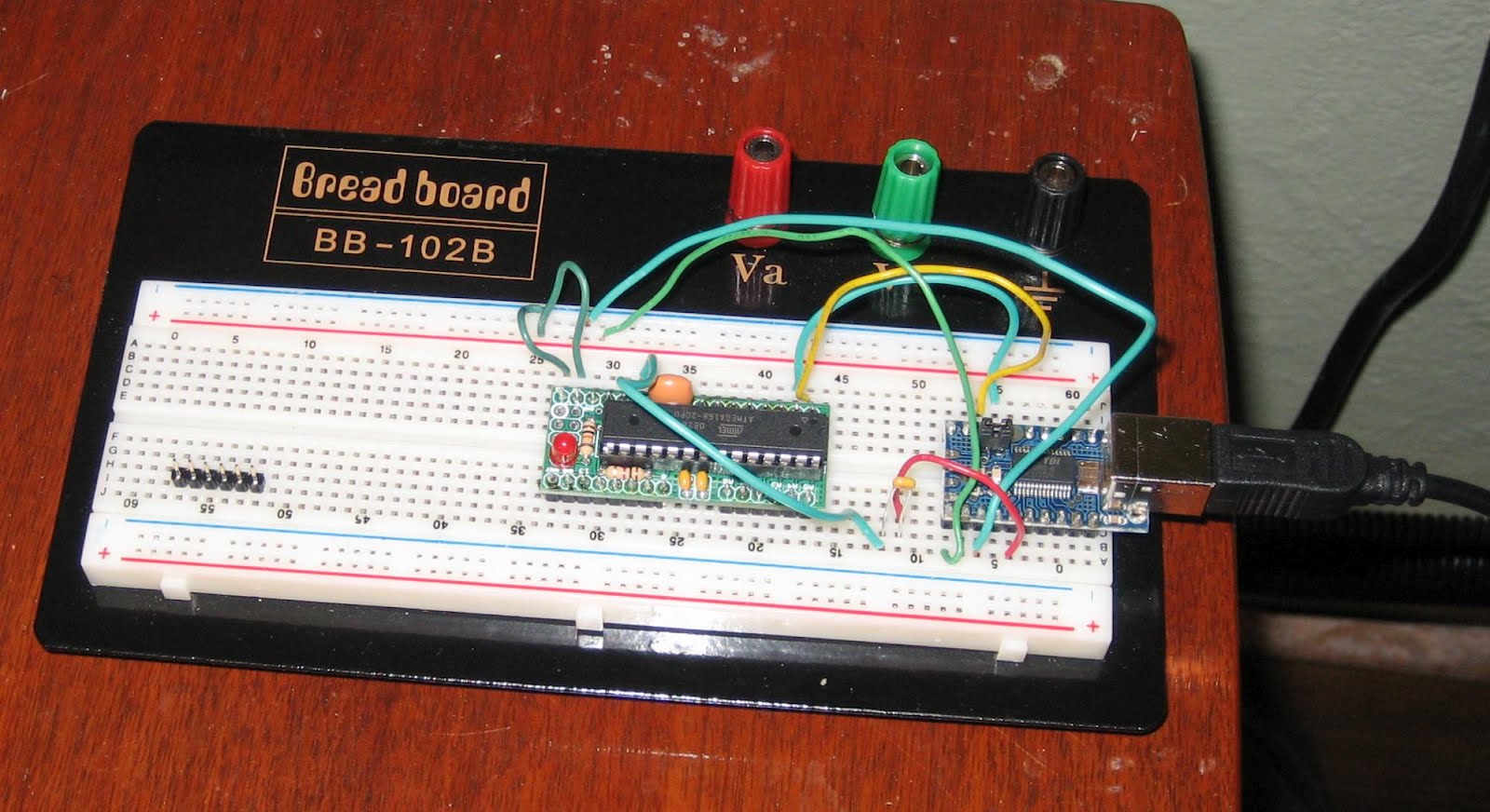
This comes as a very straightforward kit that takes all of about 15 minutes to solder up. Here is what it looks like all done up on a breadboard:


This is a very basic *Duino that doesn't include a built in USB interface (similar to the Arduino Mini, but a bit bigger). You therefore need to rig it up to an external USB to TTL serial converter, which is where I ran into a minor hiccup.

The problem is that on the new model Arduinos, they load up software very nicely and you don't need to do anything special, but with the older Arduino models you need to fiddle with the reset button at the exact right time to get them to upload new firmware. This is initially how I thought you had to use the DuinoStamp, but it was very frustrating trying to figure out the exact right timing for the reset and an error message that looks like:

avrdude: stk500_getsync(): not in sync: resp=0x60 avrdude: stk500_disable(): protocol error, expect=0x14, resp=0x66

(Whoever "Avrdude" is?). Anyway, I dropped a note to the Fundamental Logic people and Kevin got back to me right away and said the trick is to put a 0.1 uF capacitor between the RST pin on the DuinoStamp and the DTR pin on the USB adapter. Here is a rather crude scheamtic (click for full size):


So, now I can upload new firmware to the StampDuino, I shall try to port over some of my other projects to this new form factor.

Next up, I need to start describing my Xbee sensor network!